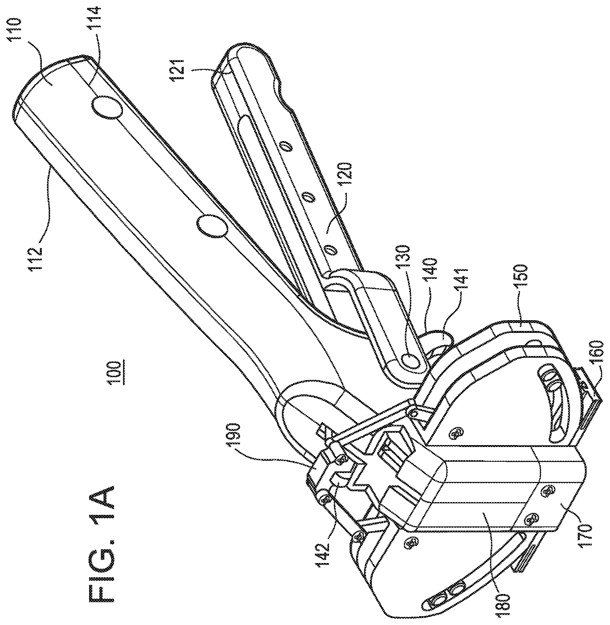
Intra dermal tissue fixation device
a tissue fixation device and dermal tissue technology, applied in the direction of mechanical equipment, surgical staples, applications, etc., can solve the problems of taking a surgeon a long time to close with sutures, time-consuming, and insufficient strength or support of the deep dermal layers while the wound is healing
- Summary
- Abstract
- Description
- Claims
- Application Information
AI Technical Summary
Benefits of technology
Problems solved by technology
Method used
Image
Examples
embodiment 200
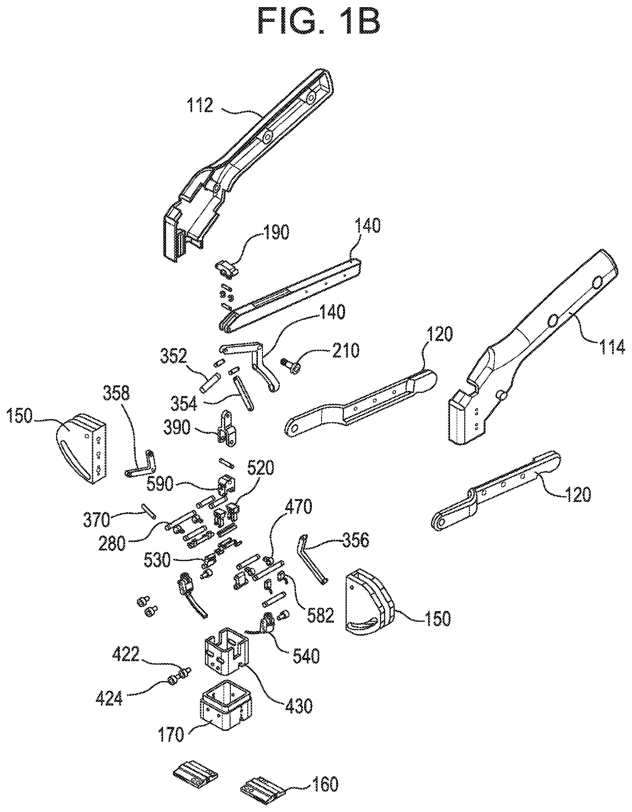
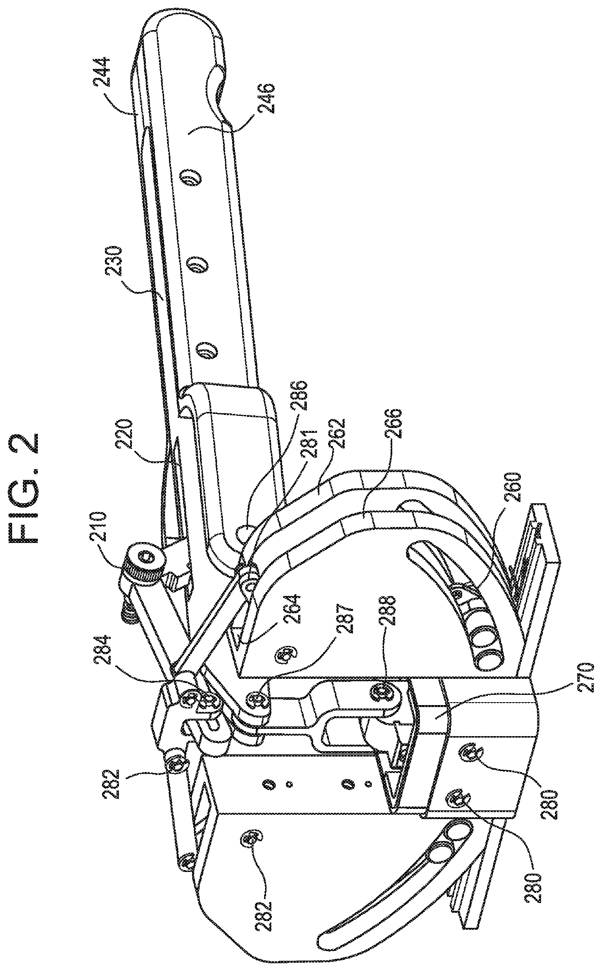
[0054]Referring to FIG. 3, the partially disassembled version 300 of the embodiment 200 of FIG. 2 is illustrated without one of the driver cam guides 150 and opposing wall support structures 262 and 264 to enable the visualization of the components typically assembled within this feature. The slot 350 in the distal end of the firing trigger 140 is shown. The slot 350 enables the slidable linkage with the center portion of the driver saddle element 190. The two lateral ends of the upper portion of the driver saddle are in pivotable engagement with two linkage bars 352 and 354. The two linkage bars 352 and 354 are in pivotable engagement with the upper ends of the acute link elements, 356 and 358. Additionally, the distal end 310 of the tissue engagement trigger slotted support bar is in pivotable engagement with the upper portion 394 of the driver yoke 390. The lower portion of the driver yoke 392 is formed in the shape of a “Y” to receive its mating component. The tissue fastener 37...
embodiment 300
[0055]Referring to FIG. 4, a partially disassembled version 400 of the embodiment 300 illustrated in FIG. 3 is provided. The axle housing is not present and the inner retractor housing 430 is shown. The device 400 includes four retractor housing cam levers 470, only one is labeled. The cam levers 470 are pivotably engaged to retractor housing through the location within the retractor housing slots 440. The opposite ends of the cam levers are pivotably engaged with their respective mating components. The retractor housing is produced with two opposed slots one of which is labeled 410. The slots 410 provide the necessary clearance to enable the retractor housing to be slidable vertically within the mating axle housing 170 element. The lower end of the acute linkage element 356 is in pivotable engagement with the stylus mount 420. The stylus mount 420 has two cam glide bearings 422 and 424 mounted to the opposite sides of the stylus mount 420. It can be seen that the cam glide bearings...
embodiment 400
[0056]Referring now to FIG. 5, a partially disassembled version 500 of the embodiment 400 detailed in FIG. 4 is provided. The balance of the linkage attachments will be detailed. The driver yoke is attached to the pivot base 590. The upper ends of four cam linkage bars 520 are pivotably attached to the pivot base 590 through the use of pins that are passed through the first pair of cam linkage bars 520 through the pivot base unit and through the second pair of cam linkage bars 520. The pins are longer than the width of the two pairs of cam linkage bars 320 and the pivot base unit. The extended ends of the pins are passed into pockets in the two opposing pivot base cap plates 510 that are fixedly attached to the pivot base. The opposite ends of the cam linkage bars 320 are pivotably attached to the cam lever extensions 594. The device is seen to have four tissue hook base elements 580. The tissue hook base element 580 is produced in an “L” shaped configuration. The thickest portion o...
PUM
 Abstract
Description
Claims
Application Information
 - R&D
- Intellectual Property
- Life Sciences
- Materials
- Tech Scout
- Unparalleled Data Quality
- Higher Quality Content
- 60% Fewer Hallucinations
Browse by: Latest US Patents, China's latest patents, Technical Efficacy Thesaurus, Application Domain, Technology Topic, Popular Technical Reports.
© 2025 PatSnap. All rights reserved.Legal|Privacy policy|Modern Slavery Act Transparency Statement|Sitemap|About US| Contact US: help@patsnap.com


