Ion probe

a technology of ion probes and probes, applied in the field of ion probes, can solve the problems of reducing the insulation resistance between metal wires, reducing the accuracy of flame detection, and the foregoing problems cannot be effectively resolved, and achieve the effect of reducing the insulation resistan

Active Publication Date: 2020-09-01
TOYOTA JIDOSHA KK
View PDF13 Cites 0 Cited by
  • Summary
  • Abstract
  • Description
  • Claims
  • Application Information

AI Technical Summary

Benefits of technology

[0005]The inventor et al. have found the following issues related to ion probes. Insulation powder provided between a metal wire and a metal sheath absorbs moisture generated in a combustion chamber. Hence, repeated flame detection, that is, repeated use of an ion probe, reduces the insulation resistance between the metal wire and the metal sheath, resulting in reduction in the accuracy of flame detection.
[0009]In the ion probe according to the above aspect of the disclosure, the ceramic capillary through which the portion of the metal wire projecting from the distal end of the metal sheath is passed is bonded to the distal end of the metal sheath by the organic adhesive layer. Thus, the organic adhesive layer is covered with the ceramic capillary. Therefore, even if the ion probe is repeatedly used, burnout of the organic adhesive layer due to flames and deterioration of the organic adhesive layer due to heat can be restrained. In addition, in the ion probe according to the above aspect of the disclosure, a part of the insulation powder located at the distal end of the metal sheath is covered with the organic adhesive layer. Thus, it is possible to restrain moisture from being absorbed into the insulation powder. That is, it is possible to restrain reduction in the insulation resistance between the metal wire and the metal sheath due to repeated use of the ion probe.
[0011]In the above aspect, the insulation powder may contain magnesium oxide powder. With this configuration, it is possible to increase the insulation resistance between the metal wire and the metal sheath.
[0013]The disclosure provides the ion probe configured to restrain reduction in the insulation resistance between the metal wire and the metal sheath due to repeated use of the ion probe.

Problems solved by technology

Hence, repeated flame detection, that is, repeated use of an ion probe, reduces the insulation resistance between the metal wire and the metal sheath, resulting in reduction in the accuracy of flame detection.
However, the ceramic adhesive layer is porous, and thus moisture permeates through the ceramic adhesive layer.
The insulation powder then absorbs the moisture, and therefore the foregoing issues cannot be effectively resolved.
On the other hand, when an organic adhesive layer is used instead of a ceramic adhesive layer, burnout of the organic adhesive layer due to flames or deterioration of the organic adhesive layer due to heat may occur, and therefore the foregoing issues cannot be effectively resolved.

Method used


Image

  • Ion probe
  • Ion probe
  • Ion probe

Examples


example embodiment

[0024]Configuration of Flame Detecting System

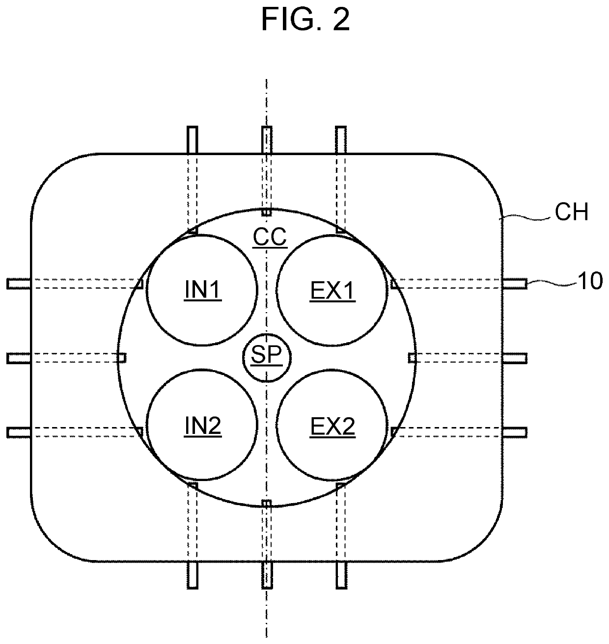
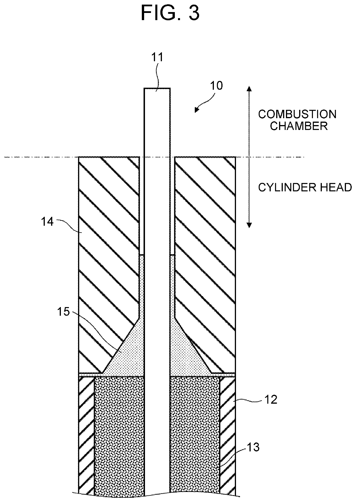
[0025]First, a flame detecting system including ion probes according to an example embodiment will be described with reference to FIG. 1. FIG. 1 is a circuit diagram of the flame detecting system including the ion probes according to the present embodiment. The flame detecting system illustrated in FIG. 1 is used to detect a flame in a combustion chamber CC of an engine. As illustrated in FIG. 1, the flame detecting system includes ion probes 10, a direct-current (DC) power source DPS, a resistor R1, a resistor R2, a capacitor C, and an output terminal OT.

[0026]As illustrated in FIG. 1, a first end of the DC power source DPS is connected to a first end of the capacitor C via the resistor R1. Further, a second end of the DC power source DPS is connected to a second end of the capacitor C via the resistor R2. That is, the resistor R1, the capacitor C, and the resistor R2 are connected in series between both terminals of the DC power source ...


PUM

PropertyMeasurementUnit
output voltageaaaaaaaaaa

Abstract

An ion probe includes a metal wire, a metal sheath covering the metal wire, insulation powder provided between the metal wire and the metal sheath, and a ceramic capillary. A portion of the metal wire projecting from a distal end of the metal sheath is passed through the ceramic capillary. The ceramic capillary is bonded to the distal end of the metal sheath by an organic adhesive layer. A part of the insulation powder located at the distal end of the metal sheath is covered with the organic adhesive layer.

Description

INCORPORATION BY REFERENCE[0001]The disclosure of Japanese Patent Application No. 2017-154105 filed on Aug. 9, 2017 including the specification, drawings and abstract is incorporated herein by reference in its entirety.BACKGROUND1. Technical Field[0002]The disclosure relates generally to an ion probe, and relates more specifically to an ion probe including a metal wire, a metal sheath covering the metal wire, and insulation powder provided between the metal wire and the metal sheath.2. Description of Related Art[0003]As described in, for example, “Development of Combustion Behavior Analysis Technique in the Ultra High Engine Speed Range” written by Takehiko Kato et al. (DENSO Corporation) and published in DENSO Technical Review, Vol. 13, No. 1, pp. 58-63 (May, 2008) (hereinafter, simply referred to as “Development of Combustion Behavior Analysis Technique in the Ultra High Engine Speed Range”), ion probes are used to detect the flame propagation behavior in a combustion chamber of a...

Claims


Application Information

Patent Timeline
Patent Type & Authority Patents(United States)
IPC IPC(8): G01N30/68H01B3/12H01B3/10G01M15/10
CPCH01B3/12H01B3/105G01M15/10F02B77/085
Inventor KUROKAWA, TOSHIKUNI
Owner TOYOTA JIDOSHA KK
Why Eureka
Try Eureka