
Random walk magnetic dielectric antenna to generate Brillouin and Sommerfeld precursors

a magnetic dielectric antenna and precursor technology, applied in the direction of antennas, antenna feed intermediates, electromagnetic transmission non-optical aspects, etc., can solve the problems of not meeting the requirements of the time, radio wave under sea water communication is restricted to very low frequency waves with very small bandwidth and consequently very low data rate, and achieves significantly less rwa length

Active Publication Date: 2020-06-09
ALFANO ROBERT
View PDF2 Cites 0 Cited by
  • Summary
  • Abstract
  • Description
  • Claims
  • Application Information

AI Technical Summary

Benefits of technology

The patent describes a new type of antenna that uses tiny particles to produce waves that can be used for communication. This antenna is much smaller and more flexible than traditional antennas, which makes it useful for underwater and underground applications. Its unique properties also make it suitable for imaging objects using a variety of frequencies.

Problems solved by technology

Optical links have proved impractical for many applications.
Although underwater radio links were experimentally evaluated in the pioneering days of radio (1), they did not meet the requirements of the time.
Therefore, the radio wave under sea water communication is restricted to very low frequency waves with very small bandwidth and consequently very low data rates.
Operating in the ELF band allowed signals to be transmitted around the earth and through the earth and sea, but at a transmission rate of only a few characters per minute and require massive antenna installations.
These services were found to be impractical in the VLF band, conventional wisdom developed that electromagnetic signals could not be used underwater.
Conventional antennas were many kilometers in length with extremely limited bandwidth.

Method used


Image

  • Random walk magnetic dielectric antenna to generate Brillouin and Sommerfeld precursors
  • Random walk magnetic dielectric antenna to generate Brillouin and Sommerfeld precursors
  • Random walk magnetic dielectric antenna to generate Brillouin and Sommerfeld precursors

Examples


Embodiment Construction

[0016]The RWA technology, which enables the generation of electromagnetic energy in a very small footprint, can provide new RF scenarios like underwater and through the ground communication and imaging, detecting mines; thus opening new business opportunities previously not viable with present antenna modalities. A new recent patent was granted on random walk antenna to the PI: Robert Alfano U.S. Pat. No. 9,620,858 B2 in 2017 for MHz, GHz and KHz [2] and small antenna units [3].

[0017]VLF radio waves can be exist after traveling ˜700 meters in seawater (using conventional antenna VLF radio waves can penetrate seawater to a depth of only up to 40 meters). The same or better can be achieved using RWA due the SP and BP Waves.

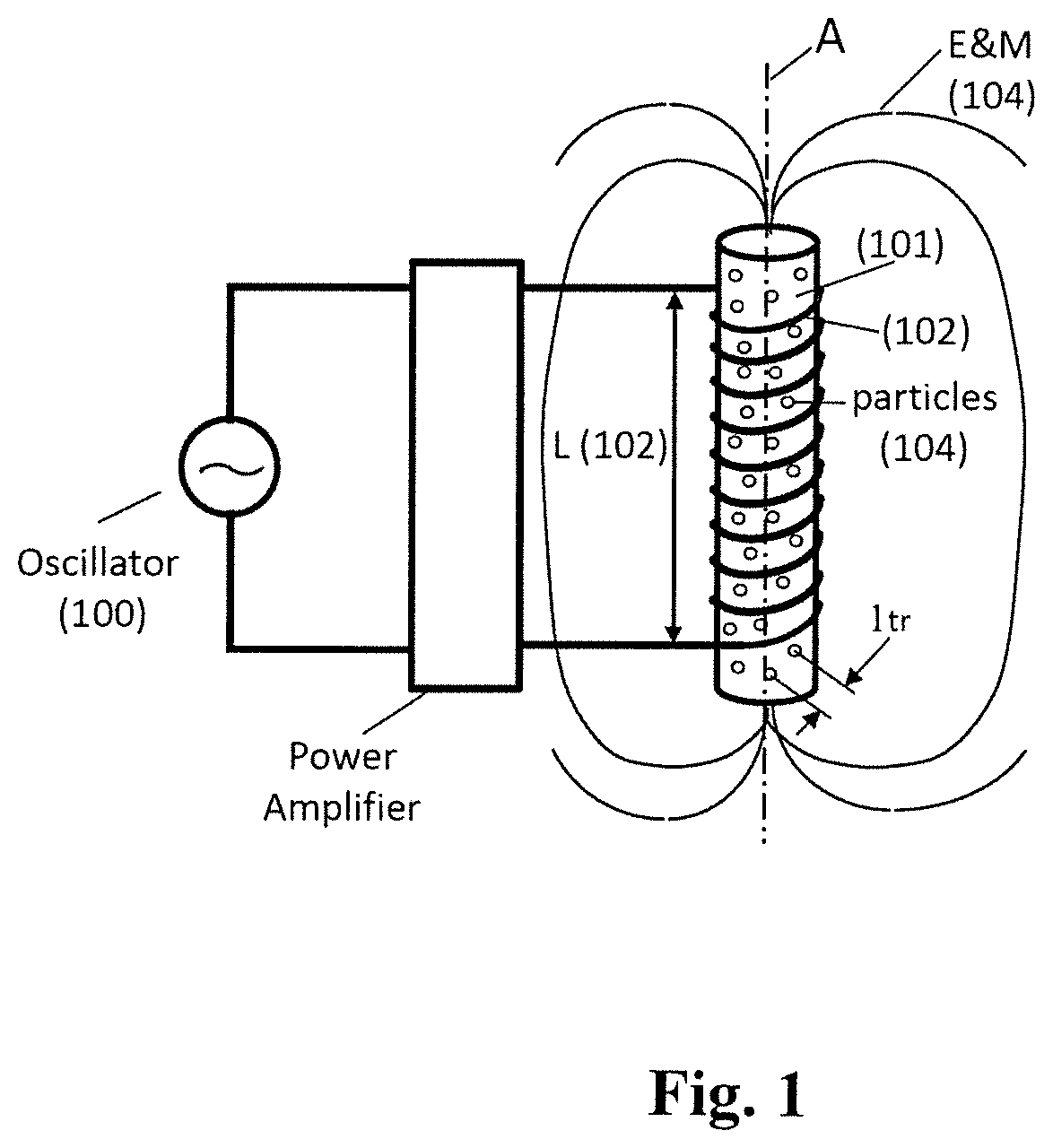
[0018]The length of the tested RWA module is 27 inches <1 meter which is four orders of magnitude smaller than conventional antenna which is ¼λ=c / 4f or 25 km. [3]

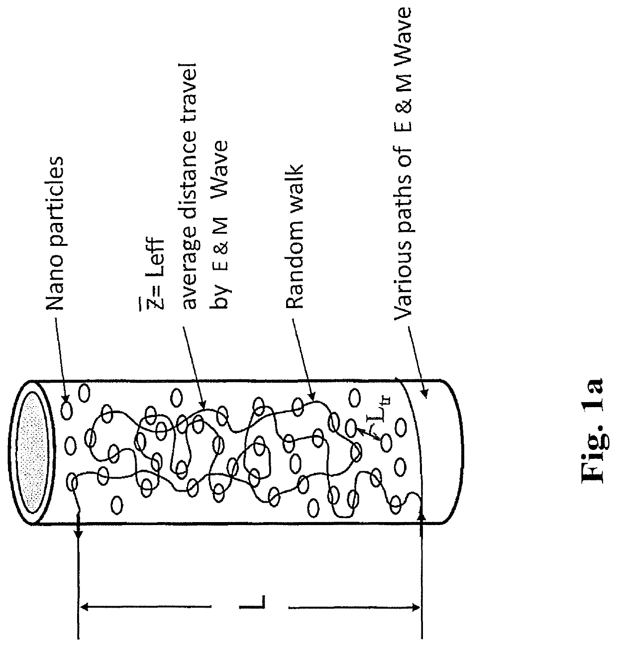
[0019]FIG. 1 shows a schematic of a compact antenna 10 in accordance to the invention. The antenna 10 ha...


PUM

PropertyMeasurementUnit
sizeaaaaaaaaaa
physical lengthaaaaaaaaaa
sizeaaaaaaaaaa

Abstract

A Random Walk Antenna (RWA) generates VLF, ULF, RF, MHz and GHz waves by dispersion of a driving signal through a ferriomagnetic ferrite nano and micron composite in compact ultra-small antenna. When oscillator frequency spans several resonances of ferrite magnetic dielectric media consisting of resonances from optical phonons and magnon high frequency and lower frequency are produced from Sommerfeld Polaritons Precursor (SP) and Brillouin Polariton Precursors (BP), respectively. The ferrite nano and micron size particle in antenna resultant electromagnetic waves from RWA contain Sommerfeld and Brillouin polariton precursors. High and low-frequency waves propagate with an algebraic attenuation making them ideal for deep use in highly conductive or highly attenuating media such as in seawater, buildings, underground and or free space on the Earth. Warfighters can use the RAW ferrite nano and micron size antenna system.

Description

BACKGROUND OF THE INVENTION1. Field of the Invention[0001]The invention generally relates generating E&M Precursors from compact electromagnetic wave antennas and, more specifically, to Random walk magnetic dielectric antenna consisting of nm and urn size particles for VLF, RF MHz and GHz regime for communications, detecting objects and imaging objects.2. Description of the Prior Art[0002]Development of compact random walk antenna (RWA) is an important advance since underwater and underground two-way RF communication, detecting objects and imaging objects, is currently is not available. The RWA is on order of <1 m in size for VLF, RF, Mhz, and GHz uses In particular, for VLF (0.3 KHz to 30 KHz) and LF (30 KHz to 300 Kz) up to MHz, the conventional size of the antenna for VLF is 100 Km. GHz can be made small for cell phones. Optical RWA involve the excitons quantum particle and bulk semicoductors such as GaAs, II _V and II-VI media. VLF and radio waves can diffract about large obs...

Claims


Application Information

Patent Timeline
Patent Type & Authority Patents(United States)
IPC IPC(8): H01Q7/08H01Q9/16H04B10/90H01Q5/22
CPCH01Q7/08H04B10/90H01Q5/22H01Q9/16
Inventor ALFANO, ROBERT
Owner ALFANO ROBERT
Learn More