
Tire

a technology of tires and wheels, applied in the field of tires, can solve the problems of deterioration of dry steering stability, block rigidity reduction, etc., and achieve the effect of dry steering stability and on-ice performan

Active Publication Date: 2020-06-09
SUMITOMO RUBBER IND LTD
View PDF49 Cites 0 Cited by
  • Summary
  • Abstract
  • Description
  • Claims
  • Application Information

AI Technical Summary

Benefits of technology

The patent aims to create a tire that can provide stable driving on both dry and icy roads.

Problems solved by technology

However, the increase in the number and the length of the sipes and the lateral grooves causes decrease of block rigidity, therefore, it is possible that the dry steering stability and the like are deteriorated, on the other hand.

Method used


Image

  • Tire
  • Tire
  • Tire

Examples


working example (example)

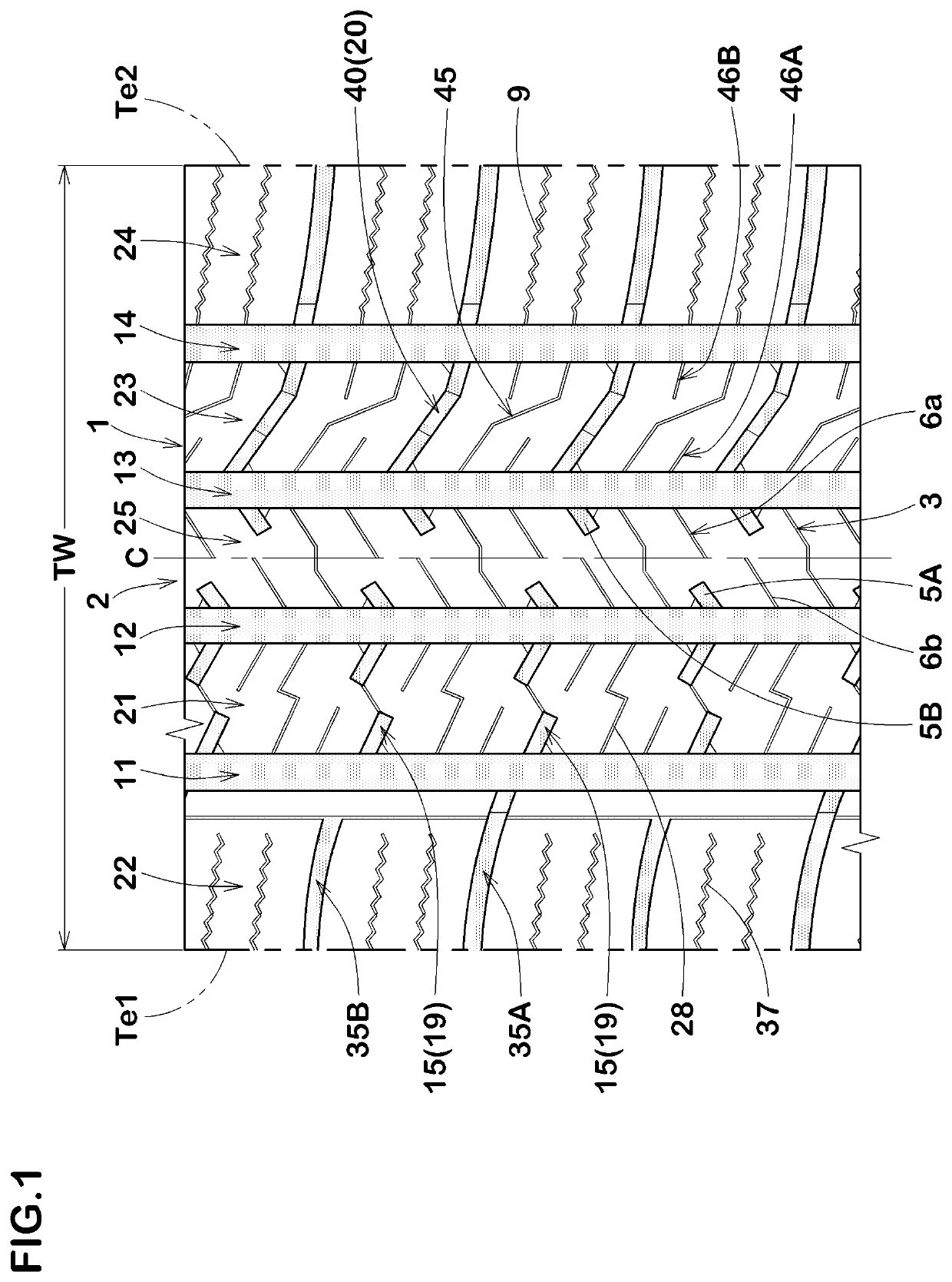
[0131]Tires of size 215 / 60R16 having a basic tread pattern shown in FIG. 1 were made by way of test according to the specification listed in Table 1. In Reference 1, as shown in FIG. 4A, the first center lateral groove 5A and the second center closed sipe 6a are not opposed to each other and the first center closed sipe 6b and the second center lateral groove 5B are not opposed to each other, whereby the high rigidity region Y is not formed. In Reference 2, the length Lb is smaller than one third of the extended length Lb0 and the length La is smaller than one third of the extended length La0, therefore, edge lengths are insufficient although the high rigidity region Y is formed. In Reference 3, the length Lb is larger than two thirds of the extended length Lb0 and the length La is larger than two thirds of the extended length La0, therefore, the high rigidity region Y is not formed. In Reference 4, the length LA is larger than a half of the extended length LA0 and the length LB is ...


PUM


Abstract

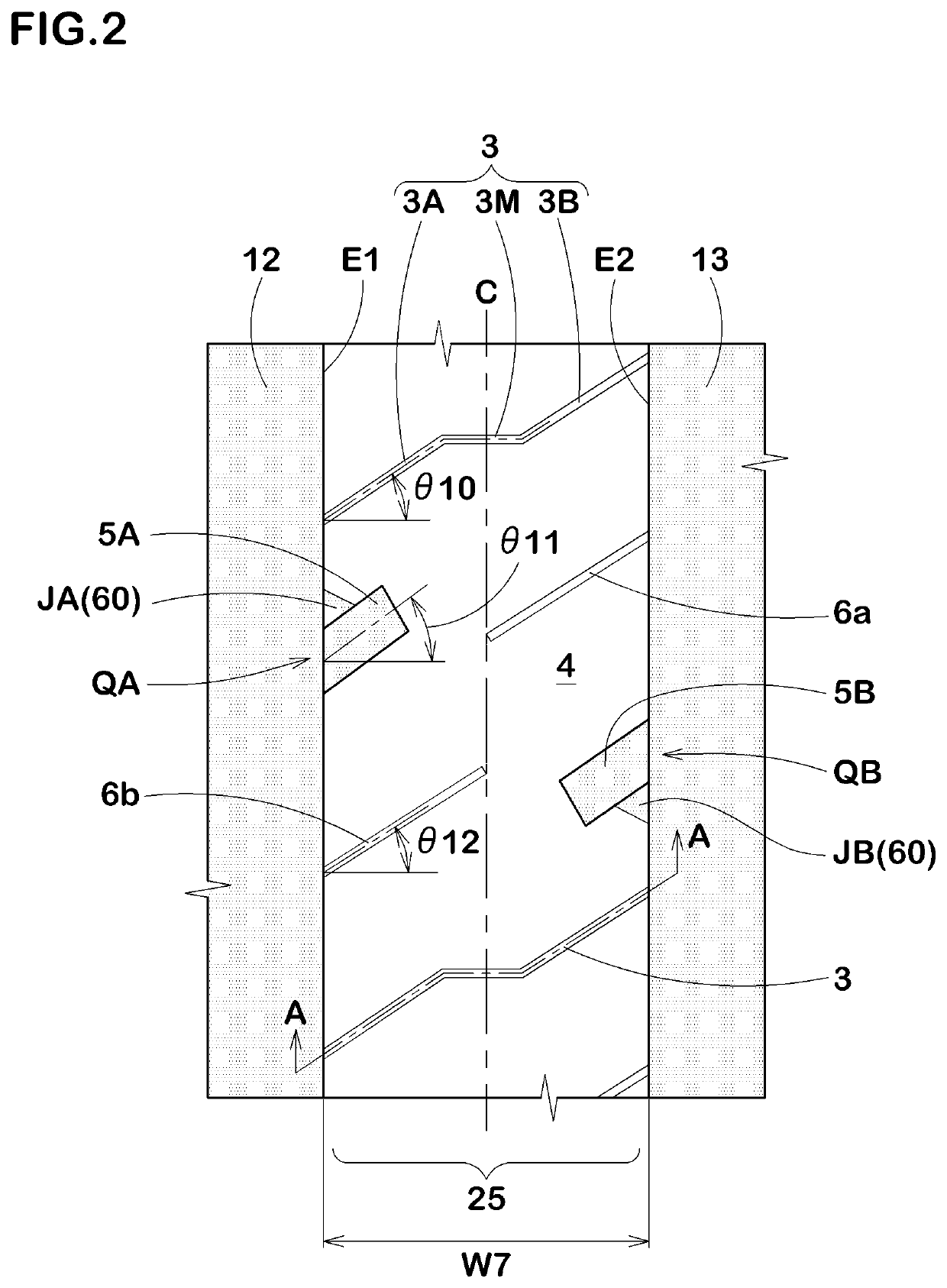
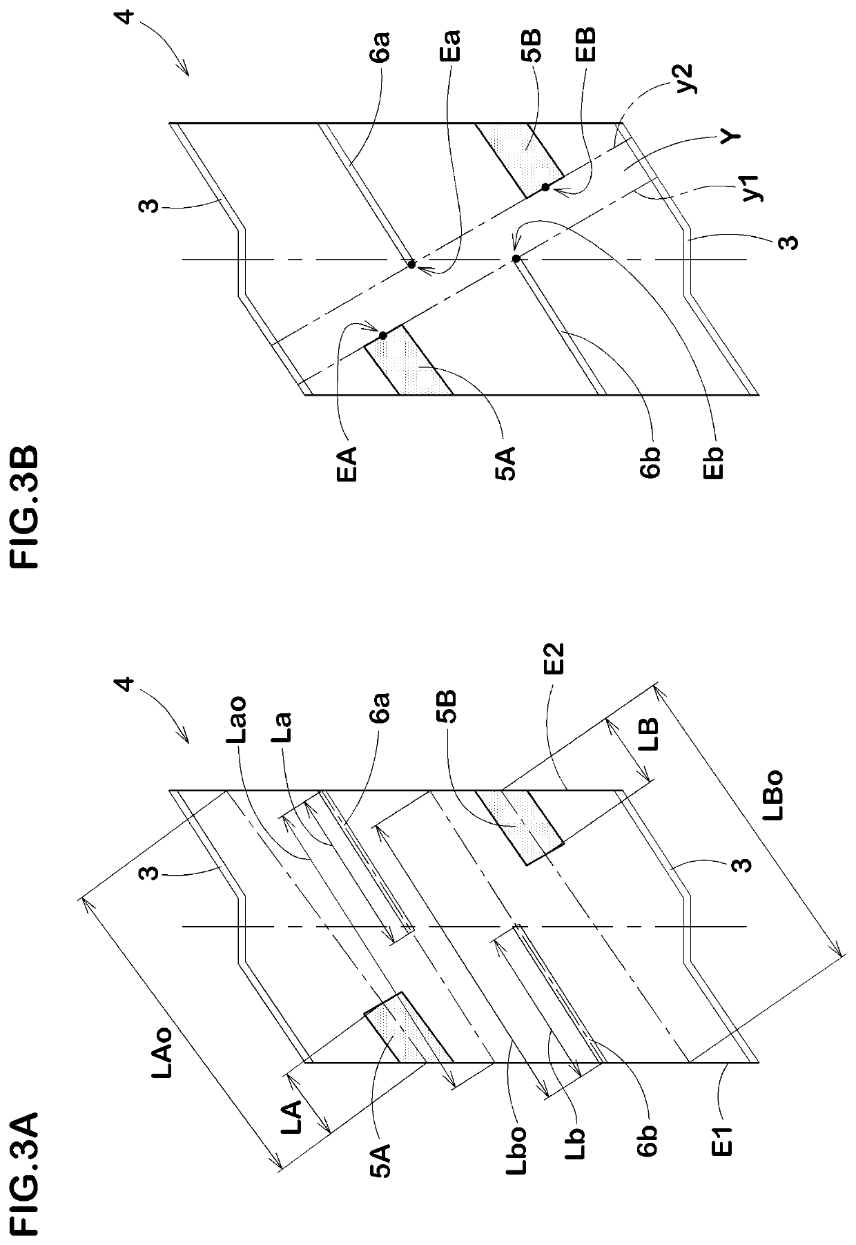
A tire comprises center blocks 4 comprising a first center lateral groove 5A and a second center closed sipe 6a opposed to each other in a tire axial direction, and a second center lateral groove 5B and a first center closed sipe 6b axially opposed to each other. Lengths thereof satisfy the followings: LA / LA0≤½, LB / LB0≤½, Lb / Lb0 in a range of from ⅓ to ⅔, La / La0 in a range of from ⅓ to ⅔, LA<La, (LA+La)<LA0, LB<Lb, and (LB+Lb)<LB0. The center blocks 4 comprise a high rigidity region extending continuously between penetrating sipes 3 and between a first imaginary line passing through terminating ends of the first center lateral groove and the first center closed sipe and a second imaginary line passing through terminating ends of the second center lateral groove and the second center closed sipe.

Description

TECHNICAL FIELD[0001]The present invention relates to a tire having both running performance on a dry road surface (hereinafter referred to as “dry steering stability”) and the running performance on an icy road surface (hereinafter referred to as “on-ice performance”).BACKGROUND ART[0002]In a tire, a large number of sipes and lateral grooves are formed in a tread portion so that the on-ice performance is secured by road surface digging frictional force (edge effect) caused by edges of the sipes and the lateral grooves (see Japanese unexamined Patent Application No. 2015-168356, for example).[0003]In order to increase the on-ice performance, formation number and length of the sipes and the lateral grooves have been increased. However, the increase in the number and the length of the sipes and the lateral grooves causes decrease of block rigidity, therefore, it is possible that the dry steering stability and the like are deteriorated, on the other hand. As just described, there is a ...

Claims


Application Information

Patent Timeline
Patent Type & Authority Patents(United States)
IPC IPC(8): B60C11/12B60C11/13B60C11/03
CPCB60C11/1384B60C11/1236B60C11/1204B60C11/1263B60C11/0306B60C11/1307B60C2011/0374B60C2011/1254B60C2011/0341B60C2011/1213B60C2011/1209B60C2011/0381B60C2011/0383B60C11/03B60C11/04
Inventor WAKIZONO, AYAYAMAOKA, HIROSHI
Owner SUMITOMO RUBBER IND LTD
Learn More