
Helical gear device

a gear device and helical technology, applied in the direction of gearing, gearing elements, hoisting equipment, etc., can solve the problems of increasing the risk of mutual meshing interference generation, considerable and the amount of backlash, so as to reduce the risk of deterioration of power transmission efficiency of helical gear devices, prevent meshing interference, and reduce the effect of backlash

Active Publication Date: 2020-05-26
TOYOTA JIDOSHA KK
View PDF7 Cites 0 Cited by
  • Summary
  • Abstract
  • Description
  • Claims
  • Application Information

AI Technical Summary

Benefits of technology

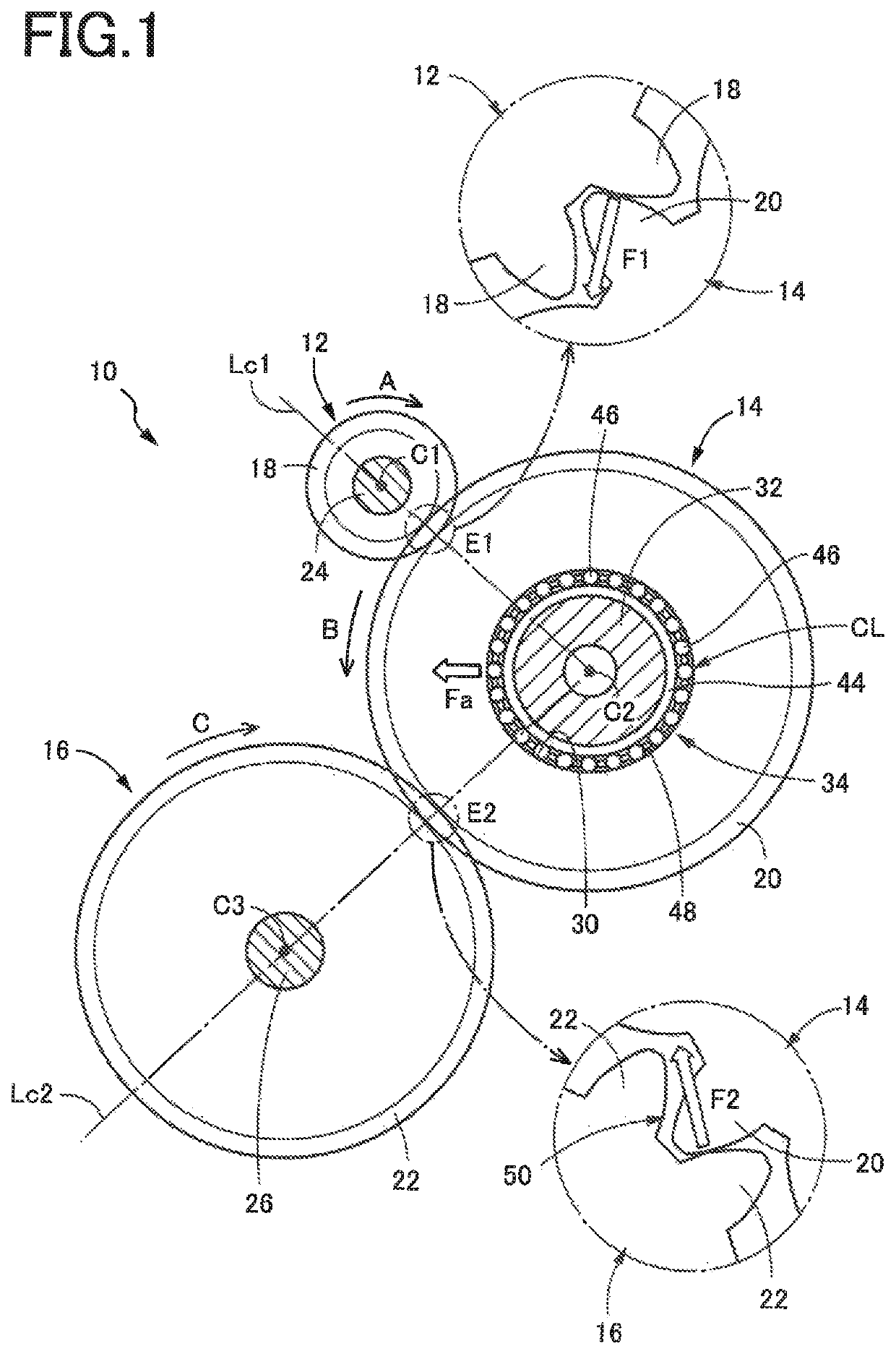
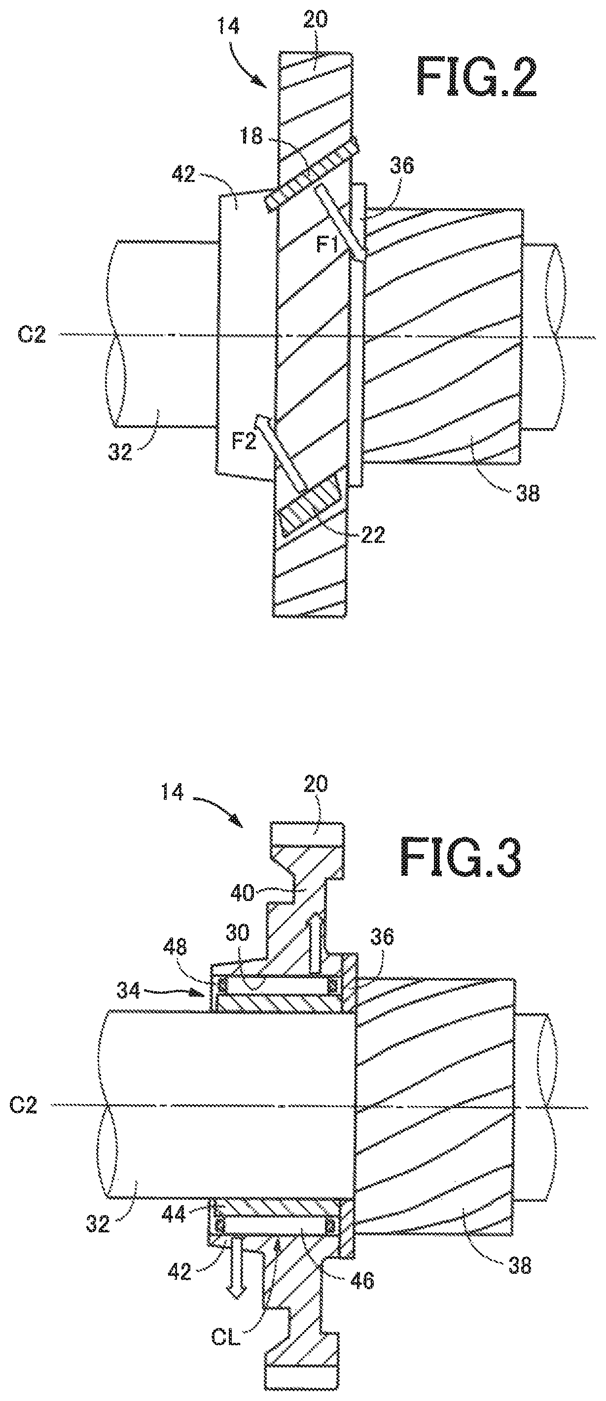
The present invention provides a helical gear device that reduces the risk of deterioration of power transmitting efficiency and durability due to mutual meshi interference between the second and third helical gears caused by concentric misalignment of the second helical gear. This is achieved by setting the radial clearance between the second and third helical gears to prevent meshing interference, even in the event of zeroing of the radial clearance due to the radial play between the second helical gear and the support shaft. The invention also provides a helical gear device that reduces the risk of deterioration of power transmitting efficiency and durability due to wearing of parts with uneven load application to the second helical gear. Additionally, the invention provides a helical gear device that reduces the risk of deterioration of power transmitting efficiency and durability even in the event of not only concentric misalignment of the second helical gear but also its inclination with respect to the second axis.

Problems solved by technology

However, the helical gear device described above suffers from a risk of concentric misalignment of the second helical gear due to a radial clearance (radial play) of the needle bearing, giving rise to generation of a mutual meshing interference between the second and third, helical gears with an amount of backlash therebetween being zeroed as a result of a movement of the second helical gear toward the third helical gear.
The risk of generation of the mutual meshing interference increases with a decrease of a preset amount of the backlash to reduce generation of a mutual tooth butting noise of the second and third helical gears.
The generation of the mutual meshing interference of the second helical gear with respect to the third helical gear causes not only considerable deterioration of efficiency of power transmission between the second and third helical gears, but also uneven load application to the second helical gear due to an axial component of a load of meshing with the first helical gear, giving rise to a risk of deterioration of durability of the helical gear device due to wearing of its various parts.
Where a thrust washer having a small diameter is disposed axially adjacent to the second helical gear, for instance, the axial component of the load of meshing with the first helical gear is boosted (amplified) according to a difference of the diametric dimension of the thrust washer with respect to the second helical gear, giving rise to a risk of application of an excessively large thrust load to the thrust washer, and consequent early wearing and damaging of the thrust washer.

Method used


Image

  • Helical gear device
  • Helical gear device
  • Helical gear device

Examples


Embodiment Construction

[0026]For example, the first helical gear is splined to an input shaft such that the first helical gear is rotated about the first axis together with the input shaft of the helical gear device, while the third helical gear is splined to an output shaft such that the third helical gear is rotated about the third axis together with the output shaft of the helical gear device. However, the first helical gear may mesh with other helical gears to or from which a rotary motion is transmitted. For example, the second helical gear is supported by a support shaft through a rolling-contact bearing, freely rotatably about the second axis. However, the second helical gear may be supported by the support shaft in various other manners with a predetermined radial clearance with respect to the support shaft, for example, supported through a plain bearing such as a bearing metal, or splined to the support shaft such that the second helical gear is rotated about the second axis together with the sup...


PUM


Abstract

A helical gear device includes: first and second helical gear respectively and rotatably disposed about first and third mutually parallel axes; a second helical gear meshing with the first and third helical gears so that a rotary motion is transmitted from the first to the third helical gear through the second, the second helical gear having a center bore; a support shaft disposed coaxially with a second axis parallel to the first, and extending through the center bore with a predetermined amount of radial play between the support shaft and the second helical gear, rotatably supporting the second helical gear. The second and third helical gears have a predetermined radial clearance in their reference meshing state in which their pitch circles contact. The radial clearance is smaller than a radial gap of a backlash between the second and third helical gears in the reference meshing state.

Description

[0001]This application claims priority from Japanese Patent Application No. 2017-112015 filed on Jun. 6, 2017, the disclosure of which is herein incorporated by reference in its entirety.FIELD OF THE INVENTION[0002]The present invention relates in general to a helical gear device, and more particularly to techniques for improving durability and power transmitting efficiency of a helical gear device wherein three helical gears, namely, a first helical gear, a second helical gear and a third helical gear are connected in series to each other.BACKGROUND OF THE INVENTION[0003]There is known a helical gear device comprising a first helical gear disposed rotatably about a first axis; a third helical gear disposed rotatably about a third axis parallel to the first axis; a second helical gear meshing with the first helical gear and the third helical gear and having a center bore; and a support shaft extending through the center bore and disposed coaxially with a second axis parallel to the ...

Claims


Application Information

Patent Timeline
Patent Type & Authority Patents(United States)
IPC IPC(8): F16H1/28F16H1/20F16H55/17
CPCF16H1/20F16H1/28F16H55/17F16H1/206F16H55/08
Inventor YORITA, HIROSHISASAKI, TAKETSUGUTSUKAMOTO, KENICHIROARAKAWA, KAZUYAHASHIMOTO, MANABU
Owner TOYOTA JIDOSHA KK
Learn More