
Lithium-doped pernigraniline-based materials

a lithium-doped, pernigraniline technology, applied in the direction of double layer capacitors, copper content reduction, electrical equipment, etc., can solve the problems of inability to isolate the completely oxidized form of polyaniline (i.e. pernigraniline), the only successful synthesized form of pernigraniline is now in the process of being successfully synthesized, and the pnb is tiny. , to achieve the effect of high chemical and physical performan

Active Publication Date: 2020-05-12
CENT NAT DE LA RECHERCHE SCI +2
View PDF6 Cites 0 Cited by
  • Summary
  • Abstract
  • Description
  • Claims
  • Application Information

AI Technical Summary

Benefits of technology

The patent text describes a new polymer material that has high chemical and physical performance, including good electronic and ionic conductivity. This material can be used as a positive electrode material, a conducting agent, or a binder without the disadvantages of current materials. The text also describes a simple and economic method for preparing this material. The new material has exceptional stability and can be used in various forms such as membranes, coatings, and thick films. The presence of amine groups in the material is due to the presence of a small amount of unreacted polyaniline, which can act as a catalyst for the reaction.

Problems solved by technology

Although the Leucoemeraldine and Emeraldine forms of polyaniline have been known and prepared for eighty years, the Pernigraniline form has only been successfully synthesized since the early nineties.
However, this method has the drawback of leading to only tiny amounts of pure PNB.
In addition, it has also been reported that this completely oxidized form of polyaniline (i.e. Pernigraniline) cannot be isolated and it decomposes while drying during its synthesis by oxidation of Emeraldine in aqueous acid media.
It is noted that Pernigraniline base cannot be obtained in situ by the implementation of a lithium battery comprising emeraldine as cathode, lithium metal as anode and a non-aqueous electrolyte since the transfer of protons is not probable to achieve electron neutrality during the redox process.
However, it has a poor cyclability since a 39% decrease of the discharge capacity is observed after 50 cycles.
Indeed, metallic lithium may be floating freely and can cause the direct reduction of polyaniline (P) instead of its deprotonation, inducing a decrease of its deprotonation rate.

Method used


Image

  • Lithium-doped pernigraniline-based materials
  • Lithium-doped pernigraniline-based materials
  • Lithium-doped pernigraniline-based materials

Examples


example 1

Preparation of a Lithium-Doped Pernigraniline Material PN-Li According to the Present Invention (i.e. First Object of the Invention) and Prepared According to the Process of the Present Invention (i.e. Second Object of the Invention)

[0283]Inside an argon-filled glove box, 2.1 g of LiPF6 were dissolved in 10 ml of propylene carbonate. To the resulting solution, 160 mg of N,N′-diphenyl-p-phenylenediamine and 100 μl of styrene were added. Then, a piece of 0.5 g of metallic lithium was introduced in the preceding solution. Then, 250 mg of polyaniline powder in the emeraldine base state (EB) was introduced in the preceding solution. The reaction was left with no agitation for 16 hours. The lithium was then removed from the reaction mixture and said reaction mixture was filtrated. A solid was recovered and washed twice with 20 ml of dimethyl carbonate (DMC) to yield 239 mg of the desired material PN-Li (95% yield).

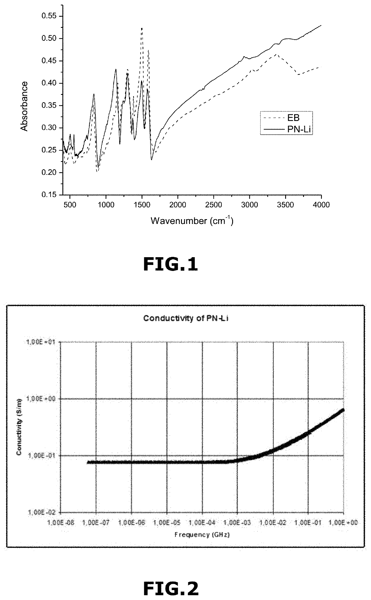
[0284]FIG. 1 represents a Fourier transform infrared spectroscopy (FTIR) of...

example 2

Preparation of a Lithium Battery (Fifth Object of the Invention) Comprising an Electrode Material E1-PN-Li According to the Present Invention (i.e. Third Object of the Invention) Prepared According to the Process of the Present Invention (i.e. Fourth Object of the Invention)

[0287]Inside an argon-filled glove box, 2.1 g of LiPF6 were dissolved in 10 ml of a dimethyl carbonate and ethylene carbonate mixture in a 1:1 volume proportion. To the resulting solution, 160 mg of N,N′-diphenyl-p-phenylenediamine and 100 μl of styrene were added. Then, a piece of 0.5 g of metallic lithium was introduced in the preceding solution. Then, 250 mg of a mixture of EB, polytetrafluoroethylene (PTFE) and vapour grown carbon fibers (VGCF) in 90:5:5 weight proportions was embedded in a stainless steel wire mesh current collector and the resulting embedded stainless steel wire was introduced in the preceding solution. The reaction was left undisturbed for 16 hours. The lithium was then removed from the re...

example 3

Preparation of a Lithium Battery (i.e. Fifth Object of the Invention) Comprising a Composite Electrode Material CE1-PN-Li According to the Present Invention (i.e. Third Object of the Invention) Prepared According to the Process of the Present Invention (i.e. Fourth Object of the Invention)

[0306]5 mg of EB were dispersed in 5 ml of N-methyl-2-pyrrolidinone. Then, 195 mg of LiFePO4 were added to the dispersion and the resulting mixture was stirred for 2 hours. Then, 25 ml of ethanol were added dropwise to the resulting mixture while stirring. The obtained mixture was filtered. A solid was recovered, washed with ethanol, and dried to yield LiFePO4 particles coated with EB (also called LFP / EB material).

[0307]FIG. 8 represents a TEM image of the obtained LFP / EB material. FIG. 8 shows the thin coating of EB covering the LiFePO4 particles.

[0308]Inside an argon-filled glove box, 1.5 g of LiPF6 were dissolved in 10 ml of a 1:1 mixture in volume of dimethyl carbonate and ethylene carbonate. T...


PUM

PropertyMeasurementUnit
weight %aaaaaaaaaa
weight ratioaaaaaaaaaa
weight %aaaaaaaaaa

Abstract

The present invention relates to a new lithium-doped Pernigraniline-based material, a method for the preparation thereof, its use in various applications, an electrode comprising said lithium-doped Pernigraniline-based material and its preparation method, a membrane comprising said lithium-doped Pernigraniline-based material and its preparation method, and an electrochemical storage system comprising said electrode.

Description

RELATED APPLICATIONS[0001]This application is a National Phase Application of PCT / EP2015 / 053689 filed on Feb. 23, 2015, which in turn claims the benefit of European Patent Application No. 14 305254.6, filed on Feb. 24, 2014 the entirety of which are incorporated herein by reference.BACKGROUNDField of the Invention[0002]The present invention relates to a new lithium-doped Pernigraniline-based material, a method for the preparation thereof, its use in various applications, an electrode comprising said lithium-doped Pernigraniline-based material and its preparation method, a membrane comprising said lithium-doped Pernigraniline-based material and its preparation method, and an electrochemical storage system (such as a battery or a supercapacitor) comprising said electrode.Description of Related Art[0003]Batteries comprising a positive electrode and a negative electrode separated by an electrolyte comprising a lithium salt in solution in a solvent are widely known. The operation of thes...

Claims


Application Information

Patent Timeline
Patent Type & Authority Patents(United States)
IPC IPC(8): H01M4/60C08G73/02C04B7/24C04B22/16C04B7/153C04B28/08C04B28/02H01M4/62H01M10/0568H01M4/74H01M4/66H01G11/06H01G11/50H01G11/86H01G11/52H01G11/60H01G11/62H01M10/0525H01M4/02C04B103/12
CPCC04B28/021C04B22/16H01G11/52H01M10/0525H01M4/606C04B7/243H01M4/669H01G11/86C04B22/064C08G73/0266H01M10/0568C04B14/06C04B28/08C04B7/153C04B12/04H01M4/623H01M4/625H01G11/60H01G11/62H01M4/747H01G11/50H01G11/06H01M2004/028C04B2103/12Y02P40/143Y02P40/145Y02P40/10Y02E60/10C04B28/02
Inventor GAUBICHER, JOËLGUYOMARD, DOMINIQUELESTRIEZ, BERNARDBONNET, JEAN-PIERREJIMENEZ MANERO, PABLO
Owner CENT NAT DE LA RECHERCHE SCI
Learn More