
Container for receiving beverages and device for filling the container

a beverage container and container technology, applied in the direction of drinking vessels, liquid transfer devices, transportation and packaging, etc., can solve the problems of large number of freshly prepared beverages, long time, and inability to provide a large amount of beverages, and achieve the effect of being easy to produ

Active Publication Date: 2020-04-07
B & B INNOVATION GMBH
View PDF18 Cites 5 Cited by
  • Summary
  • Abstract
  • Description
  • Claims
  • Application Information

AI Technical Summary

Benefits of technology

The present invention aims to provide a container that is affordable to produce, can be quickly filled with a beverage, and then securely sealed after filling. Additionally, the invention aims to provide an apparatus that can fill such a container with a wide range of beverages that are easy to use, cost-effective, and long-lasting.

Problems solved by technology

In particular, at large events with a high number of visitors, the need often arises to provide a very large number of freshly prepared beverages to the visitors to the event within an extremely short time.
Since the breaks at such events are often very limited in time, it is often not possible in practice to provide a great number of people with the appropriate beverages in a timely manner, since the filling of conventional containers, such as drinking cups, for example, with a freshly drawn beer or a freshly tapped soft drink often takes a long time.
It is not therefore possible to provide a large amount of beverages in a timely manner with only a manageable number of taps.
However, it is disadvantageous that such containers are extremely expensive both to produce and to subsequently dispose of, since the metal part that coacts with the magnetic plate must be elaborately incorporated into the appropriately shaped bottom of the container and separated again from the bottom at the time of disposal.

Method used


Image

  • Container for receiving beverages and device for filling the container
  • Container for receiving beverages and device for filling the container
  • Container for receiving beverages and device for filling the container

Examples


Embodiment Construction

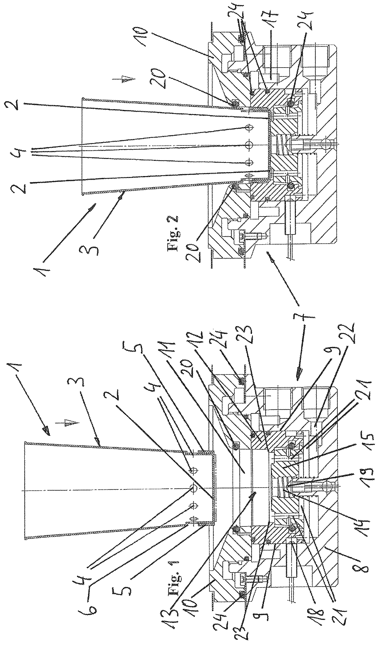
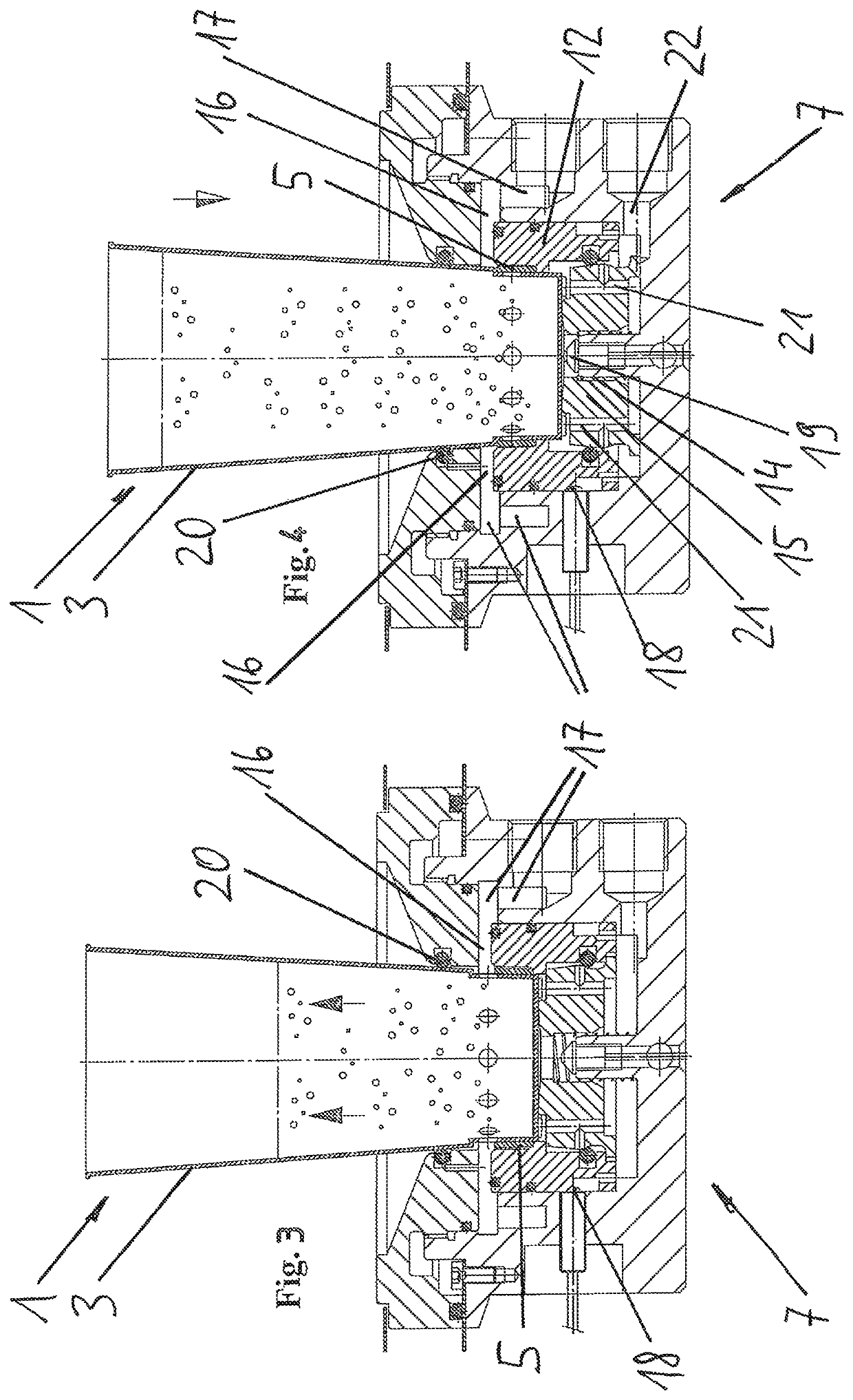
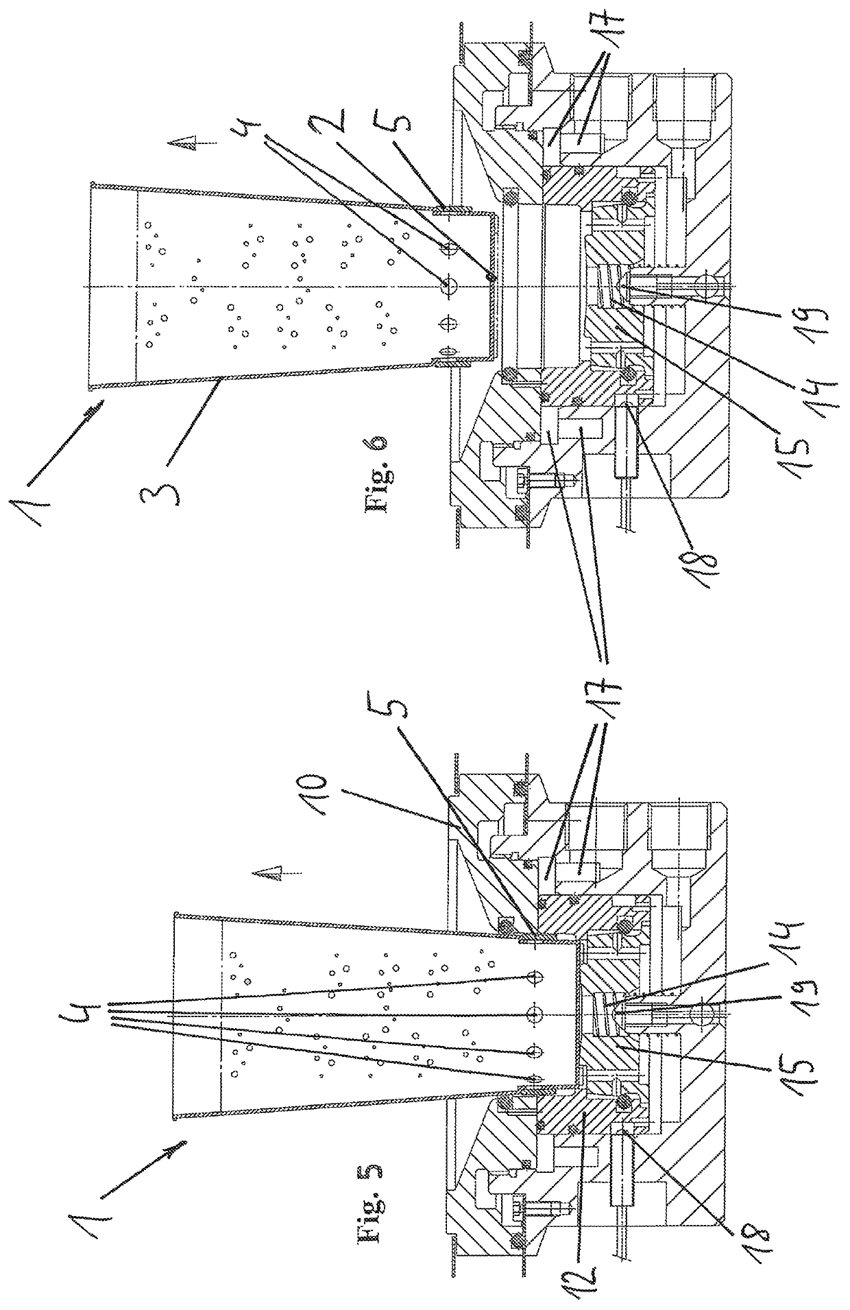
[0080]For one, the figures show a container 1 for holding a beverage. In this embodiment, the container 1 is a drinking cup. The drinking cup has at least one bottom 2 and one side wall 3 that projects approximately perpendicularly upward from the bottom 2.

[0081]According to the invention, the wall 3 of the container 1 has perforations 4. The container 1 can be filled with a beverage through the perforations 4. Once filling has been completed, the perforations 4 can be sealed by a seal element that can be applied externally to the lateral surface of the wall 3. Such a container 1 can be filled in an especially quick and easy manner by supplying pressurized beverage through the perforations 4 in the wall 3. In this embodiment, all of the perforations 4 are at the same spacing from the bottom 2 of the container 1 and are distributed angularly uniformly around the circumference of the wall 3. The perforations 4 of the wall 3 are arranged in a region of the wall 3 that is near the botto...


PUM


Abstract

According to the invention, in order to create a container (1) for receiving beverages, in particular a drinks container or drinks cup, at least comprising a base (2) and a circumferential wall (3) projecting approximately perpendicularly from the base (2), which can be produced particularly inexpensively, can be filled within a minimum time and can be securely sealed after the filling, the wall (3) has openings (4) via which the container (1) can be filled with a beverage, wherein the openings (4) can be closed after the filling via a sealing means that is / can be applied from outside to the outer surface of the wall (3). The invention also relates to a device that can fill a container of this type with a corresponding beverage, such as beer or a soft drink, within a minimum time, said device being simple to operate, inexpensive and simple to produce and having a long service life.

Description

CROSS REFERENCE TO RELATED APPLICATIONS[0001]This application is the US-national stage of PCT application PCT / DE2016 / 100572 filed 12 Dec. 2016 and claiming the priority of German patent application 202015106931.6 itself filed 18 Dec. 2015.FIELD OF THE INVENTION[0002]The invention relates to a container for holding a beverage, particularly a drinking vessel or a drinking cup, comprising at least a bottom and a circumferential wall projecting approximately perpendicularly from the bottom.[0003]In addition, the invention relates to an apparatus for filling such a container with beer or a soft drink with particular speed and ease.BACKGROUND OF THE INVENTION[0004]In particular, at large events with a high number of visitors, the need often arises to provide a very large number of freshly prepared beverages to the visitors to the event within an extremely short time. During a major sporting event, for example, several thousand beverages must be dispensed during a break, since a number of ...

Claims


Application Information

Patent Timeline
Patent Type & Authority Patents(United States)
IPC IPC(8): B65D1/40A47G19/22B67D1/08B67D1/12B67D1/06B67D1/00B67D7/44B67D3/00B65D25/00
CPCB67D1/06B67D1/1272B67D1/0003B67D1/0894B67D1/0082B67D1/001A47G19/2205B65D25/005B65D1/40B67D2001/0094B67D2001/0095
Inventor BOLENDER, DIRK
Owner B & B INNOVATION GMBH
Learn More