
Mobile equine limb inertial sensing systems and methods

Active Publication Date: 2020-04-07
CADENCE DYNAMICS LLC
View PDF7 Cites 6 Cited by
  • Summary
  • Abstract
  • Description
  • Claims
  • Application Information

AI Technical Summary

Benefits of technology

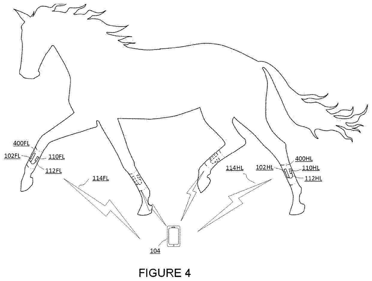
The present invention is about a system and method for measuring and analyzing the motion of a horse's limbs. A conformal biosensor device is attached to the lower legs of the horse to capture the movement of the limbs. The device is designed to be lightweight and minimize vibrations, making it easier to detect changes in the horse's gait. The system can collect, segment, and process the motion data to detect abnormal patterns in the gait that may indicate lameness or poor quality. The data analysis and reporting module is available on portable devices, making it easy for anyone to operate the system and provide immediate feedback. The system can identify the affected limb or limbs and characterize the type and severity of lameness. The horse itself can serve as its own reference for consistency and symmetrical movement between the left and right, front and hind limbs. The reported metrics can be easily understood by veterinary professionals and horse owners. The system can also be used for humans and other animals.

Problems solved by technology

Mild lameness in horses is difficult to detect and monitor for changes using standard subjective evaluation methods such as visual observation of the horse in motion.
Additionally, interference with the horse's natural head motion may occur when horse handlers pull on the lead rope during the gait evaluation session in order to slow an eager horse or to turn them on a circle during lunging.
However, the all-encompassing approach to the system may hamper sensitivity and repeatability in detecting and monitoring subtle lameness.
As the devices were not designed to be mounted to specific locations, secure attachment and proper orientation may be problematic.
A high volume of data collected can also lead to spurious correlations that may be an artifact of the data and neither biologically nor clinically insightful.
This may be necessary for gaining a full understanding of equine limb inertia patterns, but may also present challenges with separating true signals from spurious signals (e.g. vibrations due to poor coupling and the like), along with interpreting signal data.
Filtering may lead to abstracting the data away from the true signal and imposing bias in the amplitude and phase of the raw signal.
Additionally, the relatively low sampling rate (i.e. 200 Hz) may lead to missing rapidly changing signals with higher frequency content (e.g. during impact and breakover or the like).
The type of sensors used on this device (e.g. piezoelectric accelerometer) have limited low frequency response, rendering them insensitive to accurate measurement of limb motions during swing and weight bearing phases which are predominated by slowly changing signals.
This can present a problem if the halter is loose or the coat isn't properly cleaned prior to attachment (perhaps resulting in the presence of dirt, loose hair, oil, or the like), as close coupling of the device to the horse may be significant to measurement accuracy and repeatability.
It may be difficult to complete the calibration as needed to prevent synchronization drift for devices exposed to changing temperatures as perhaps in the Hodgins references.
Attachment of devices to horse limbs presents unique challenges.
The shape, size & weight (e.g., form factor) of the devices and limb attachment methods described in past systems do not appear to be well suited for sustaining relatively high equine limb acceleration, vibration, impact forces, or the like.
A limitation of this filtering is that it may corrupt the original signal in both amplitude and phase to varying degrees throughout the stride dependent on frequency content.
The computer equipment often needed to perform inertial signal processing and analysis may present a challenge for convenient operation in the field, perhaps under time and mobility constraints.
This additional computing subsystem, necessary to analyze and report the data, could be difficult to carry and operate under field conditions and may add to overall system complexity.

Method used


Image

  • Mobile equine limb inertial sensing systems and methods
  • Mobile equine limb inertial sensing systems and methods
  • Mobile equine limb inertial sensing systems and methods

Examples


Embodiment Construction

[0025]The present invention includes a variety of aspects, which may be combined in different ways. The following descriptions are provided to list elements and describe some of the embodiments of the present invention. These elements are listed with initial embodiments, however it should be understood that they may be combined in any manner and in any number to create additional embodiments. The variously described examples and preferred embodiments should not be construed to limit the present invention to only the explicitly described systems, techniques, and applications. Further, this description should be understood to support and encompass descriptions and claims of all the various embodiments, systems, techniques, methods, devices, and applications with any number of the disclosed elements, with each element alone, and also with any and all various permutations and combinations of all elements in this or any subsequent application.

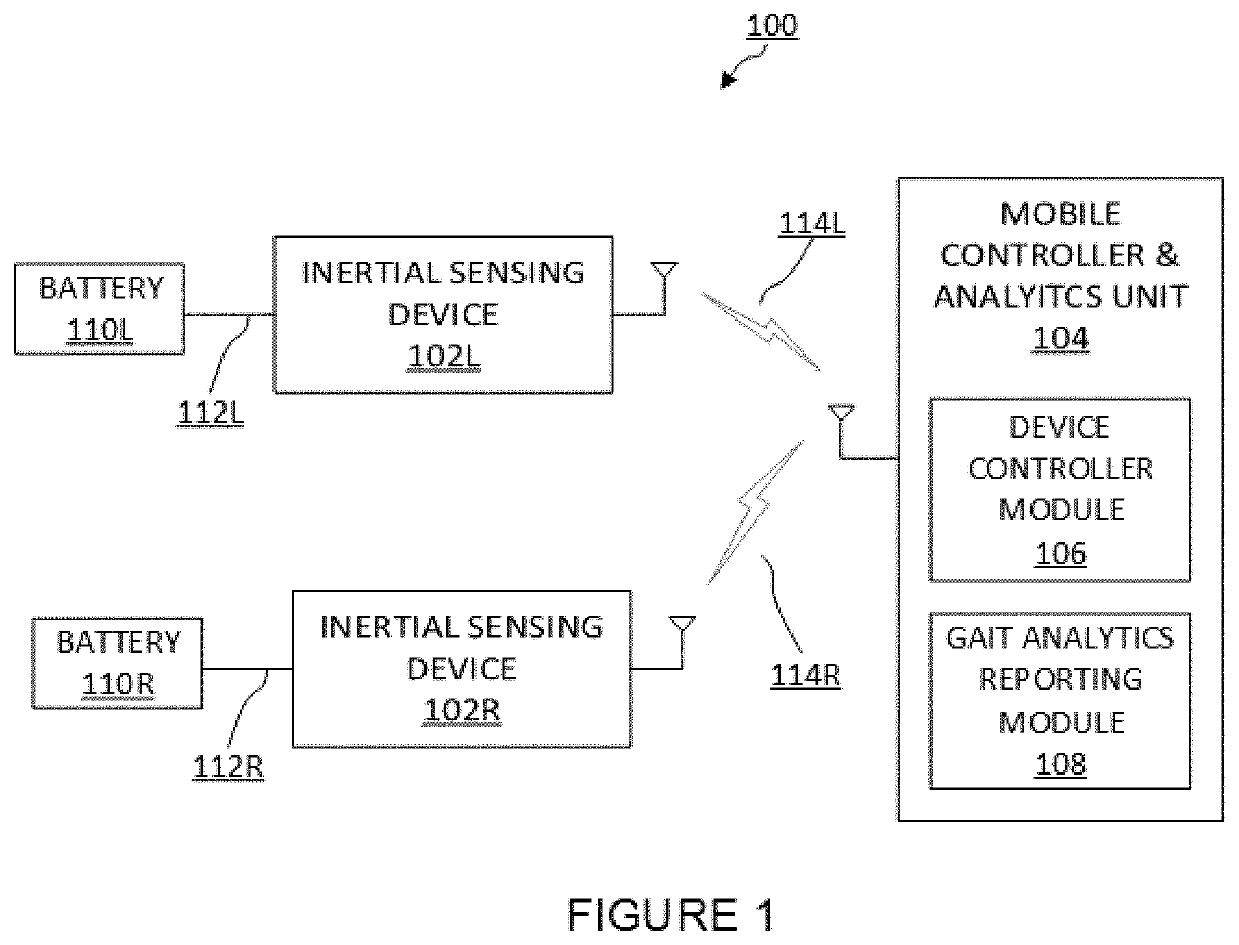
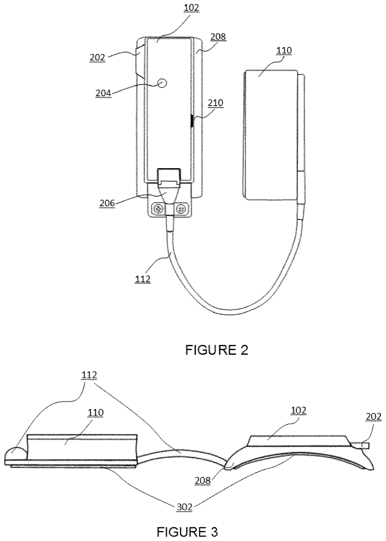
[0026]FIG. 1 illustrates an example of an equ...


PUM


Abstract

Embodiments of the present invention may provide a limb motion sensor system (100) used to objectively assist detection of equine lameness and even monitor change in gait quality over time. Biosensors (102) may be attached to the pair of front and / or hind limbs. Each conformally shaped biosensor device may be placed lateral to the metacarpal / metatarsal bone (e.g., attached to the lower limb). Inertial data may be collected by the set of sensor devices and may be wirelessly transferred to a portable, perhaps wearable, mobile controller and analytics unit (104) (e.g., smart phone, tablet, or the like). A signal processor application (108) may automatically segment each stride into phases and perform analyses to quantify limb motion metrics and uniformity over time for a single limb (unilateral consistency) or between the contralateral limbs (bilateral symmetry). Three-dimensional motion metrics may be processed, displayed, stored on, and even transmitted from the mobile information system.

Description

PRIORITY CLAIM[0001]This application is a United States nonprovisional utility application claiming priority to and the benefit of U.S. Provisional Application No. 61 / 989,368 filed May 6, 2014, hereby incorporated by reference herein in its entirety.BACKGROUND[0002]Mild lameness in horses is difficult to detect and monitor for changes using standard subjective evaluation methods such as visual observation of the horse in motion. The purpose of visual and riding-based lameness evaluations is to detect abnormal, asymmetric gait patterns. Biosensing technology could be used to both objectively measure asymmetric gait patterns and monitor a change in gait suggestive of lameness. These types of sensing instruments should be reliable (e.g., characterized by accuracy, repeatability, sensitivity, specificity, or the like) and easily applicable by both horse owners and veterinarians.[0003]The main output from two commercially available lameness detection devices may be derived from two motio...

Claims


Application Information

Patent Timeline
IPC IPC(8): A61B5/11A61B5/00
CPCA61B5/112A61B5/6828A61B2503/40A61B2562/0219
Inventor THOMPSON, JOHN D.ESTBERG, LEAH
Owner CADENCE DYNAMICS LLC
Learn More