Relay
a technology of relays and relays, applied in the field of relays, can solve the problems of compact construction and the need to miniaturize the same even further, and achieve the effects of less space, reliable, long-term operation and convenient assembly
- Summary
- Abstract
- Description
- Claims
- Application Information
AI Technical Summary
Benefits of technology
Problems solved by technology
Method used
Image


Examples
Embodiment Construction
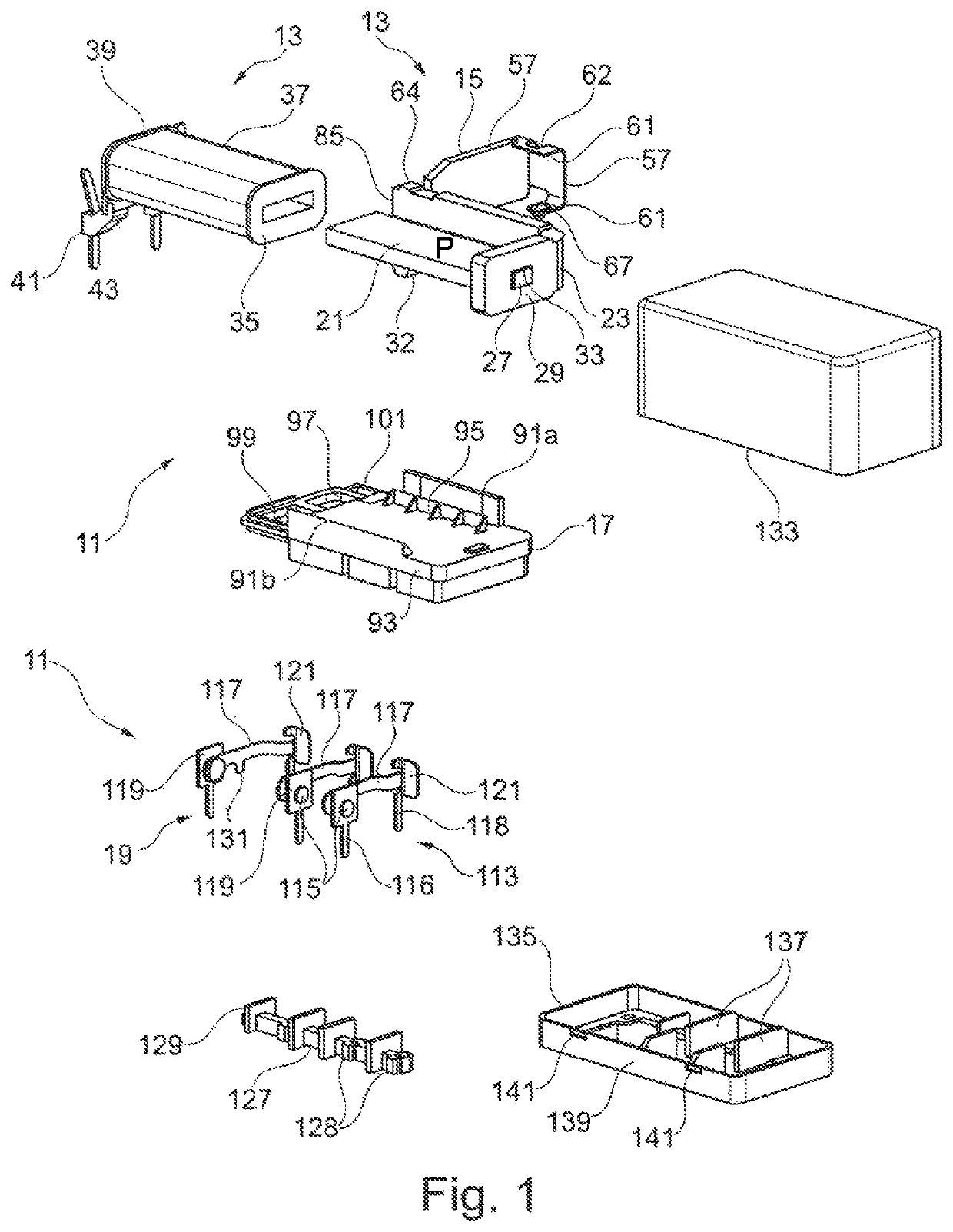
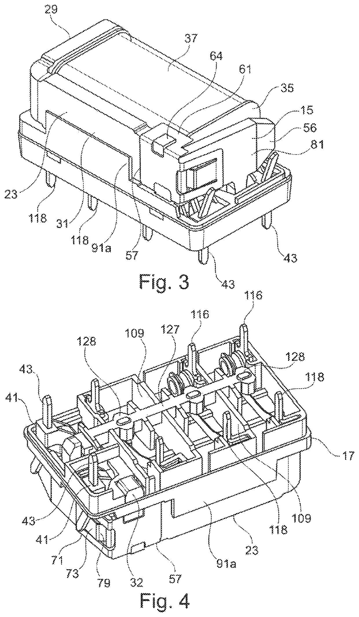
[0037]The essential components of the relay 11 shown in FIGS. 1 to 8 are an electromagnetic drive 13, an armature 15 which can be actuated by the electromagnetic drive 13, an intermediate base or partition 17, and a contact arrangement 19, which are described in more detail below in this order.
[0038]The electromagnetic drive 13 comprises a flat iron core 21 and a yoke 23 arranged on the same. Both the iron core 21 and the yoke 23 are made of one flat piece of ferromagnetic iron. The iron core 21 is rectangular when viewed from above, and a projection 27 is included (FIG. 8) in the center of a narrow side 25. The yoke 23 has an L-shape with a short limb 29 and a long limb 31, wherein the center planes of the two limbs 29, 31 are perpendicular to the center plane P of the iron core 21. A positioning pin 32, projecting at a right angle, is included on the free end of the long limb 31, the function of which is described in more detail further below.
[0039]For the connection of the iron c...
PUM
 Abstract
Description
Claims
Application Information
 - R&D
- Intellectual Property
- Life Sciences
- Materials
- Tech Scout
- Unparalleled Data Quality
- Higher Quality Content
- 60% Fewer Hallucinations
Browse by: Latest US Patents, China's latest patents, Technical Efficacy Thesaurus, Application Domain, Technology Topic, Popular Technical Reports.
© 2025 PatSnap. All rights reserved.Legal|Privacy policy|Modern Slavery Act Transparency Statement|Sitemap|About US| Contact US: help@patsnap.com