Display device and control method for the same
a display device and control method technology, applied in the field of display devices and control methods, can solve the problems of high power consumption of smart glasses, tiresome use of smart glasses, frequent charging of smart glasses, etc., and achieve the effect of enhancing the convenience of use, and enhancing the control method
- Summary
- Abstract
- Description
- Claims
- Application Information
AI Technical Summary
Benefits of technology
Problems solved by technology
Method used
Image

Examples
first embodiment
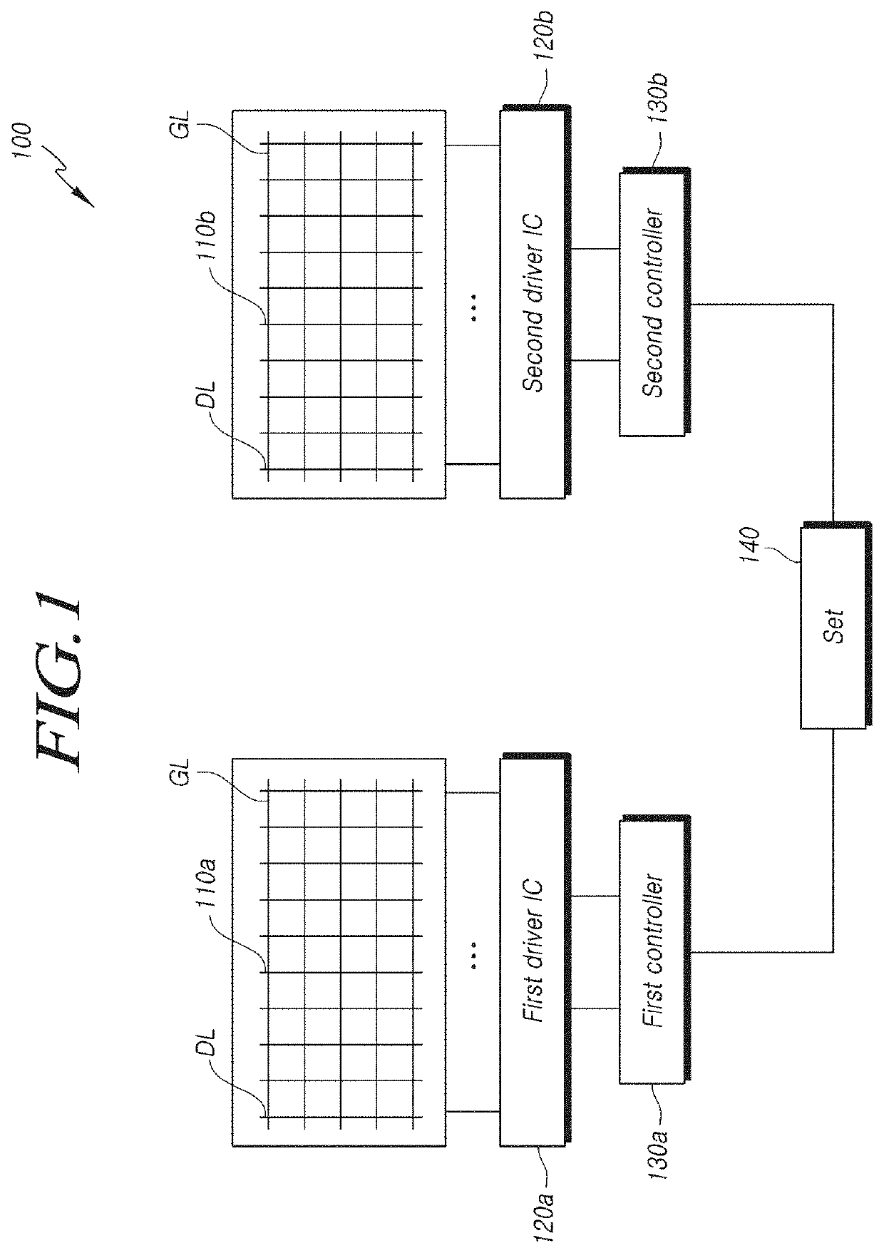
[0031]FIG. 1 is a structural diagram illustrating a display device according to the present invention. All the components of the display device according to all embodiments of the present invention are operatively coupled and configured.
[0032]Referring to FIG. 1, a display device 100 can include a first display 110a, a second display 110b, a first driver IC 120a, a second driver IC 120b, a first controller 130a, and a second controller 130b.
[0033]The first display 110a and the second display 110b can have a plurality of data lines (DL) and a plurality of gate lines (GL), which intersect each other, and pixels, which are formed at intersections of the plurality of data lines (DL) and the plurality of gate lines (GL). Each pixel can include sub-pixels for displaying any color among red, green, blue, or white. The pixel can include a pixel circuit that generates a driving current and an organic light-emitting diode that emits light through the flow of driving current. The plurality of...
second embodiment
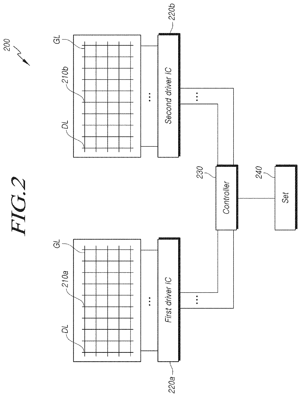
[0042]FIG. 2 is a structural view illustrating a display device according to the present invention.
[0043]A display device 200 shown in FIG. 2 is different from the display device 100 shown in FIG. 1 in that a first display 210a and a second display 210b are controlled by a single controller 230. Since the single controller 230 controls both the first driver IC 220a and the second driver IC 220b, the first driver IC 220a and the second driver IC 220b are not required to be synchronized, and thus wiring between a set 240 and the controller 230 can be simpler than the display device 100 shown in FIG. 1.
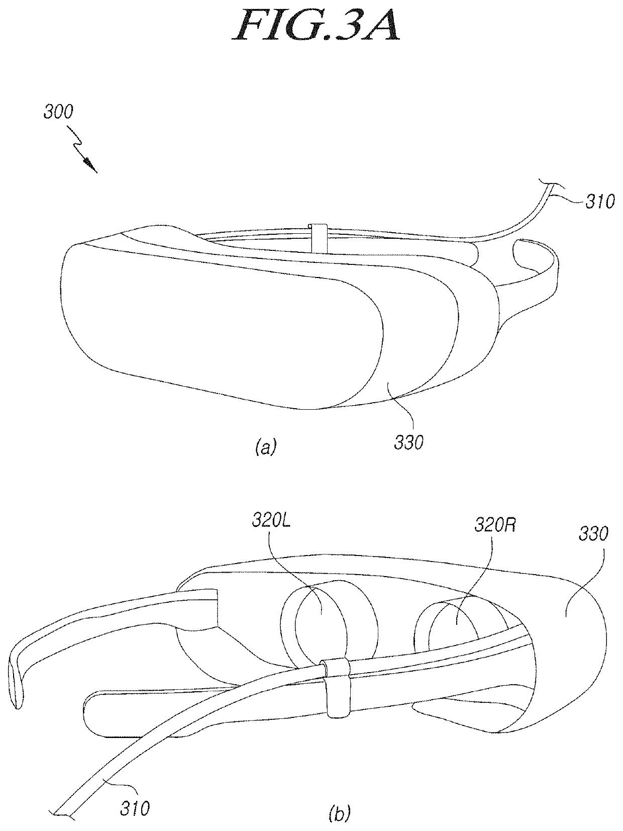
[0044]FIG. 3A is a conceptual diagram illustrating an embodiment of a virtual reality (VR) device adopting the display device shown in FIG. 1.
[0045]Referring to FIG. 3A, (a) is a perspective view of a VR device 300 when viewed from the front, and (b) is a perspective view of the VR device when viewed from the rear. The VR device 300 can include a first lens 320R and a second lens 320L co...
third embodiment
[0093]FIG. 10 is a structural diagram illustrating a display device according to the present invention.
[0094]Referring to FIG. 10, only a first display 1100, first driver ICs 1200a and 1200b for driving the same, and a first controller 1300 of the display device 1000 are shown, while a second display, second driver ICs for driving the same, and a second controller are not shown in the drawing because they can have the same configuration.
[0095]The first driver ICs 1200a and 1200b of the display device 1000, which apply driving signals to the first display 1100, can include an odd-numbered driver IC 1200a for applying driving signals to odd-numbered columns of the first display 1100 and an even-numbered driver IC 1200b for applying driving signals to even-numbered columns of the first display 1100. Although the odd-numbered driver IC 1200a and the even-numbered driver IC 1200b are illustrated herein as being disposed on the left and right sides of the first display 1100, respectively,...
PUM
 Abstract
Description
Claims
Application Information
 - Generate Ideas
- Intellectual Property
- Life Sciences
- Materials
- Tech Scout
- Unparalleled Data Quality
- Higher Quality Content
- 60% Fewer Hallucinations
Browse by: Latest US Patents, China's latest patents, Technical Efficacy Thesaurus, Application Domain, Technology Topic, Popular Technical Reports.
© 2025 PatSnap. All rights reserved.Legal|Privacy policy|Modern Slavery Act Transparency Statement|Sitemap|About US| Contact US: help@patsnap.com