Electrically isolated system and method for digital regulation of a programmable lighting device

a technology of programmable lighting and electric isolation, applied in the field of electric isolation system for digital dimming of programmable lighting devices, can solve problems such as problems such as problems such as the use of non-volatile memory

Active Publication Date: 2019-12-31
UNIVERSAL LIGHTING TECHNOLOGIES
View PDF18 Cites 3 Cited by
  • Summary
  • Abstract
  • Description
  • Claims
  • Application Information

AI Technical Summary

Benefits of technology

[0007]It is accordingly desired to provide a lighting device such as an LED driver with a wireless communication interface having adequate functionality to support or otherwise provide a continuous digital dimming interface to external dimming control devices.

Problems solved by technology

As previously noted, the use of non-volatile memory is problematic for the continuous data transfer needed for continuous digital dimming interfaces.

Method used


Image

  • Electrically isolated system and method for digital regulation of a programmable lighting device
  • Electrically isolated system and method for digital regulation of a programmable lighting device
  • Electrically isolated system and method for digital regulation of a programmable lighting device

Examples


Embodiment Construction

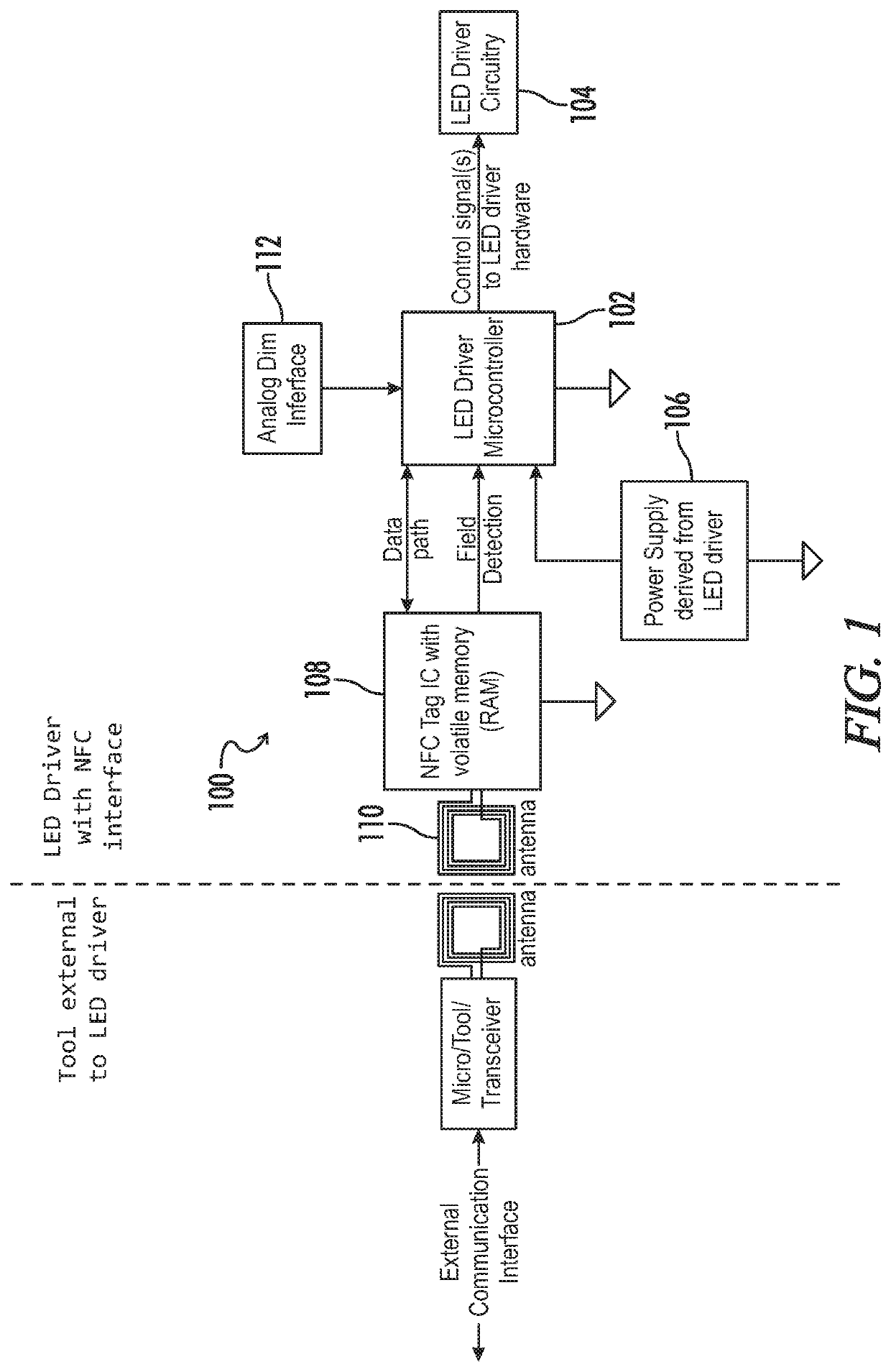
[0041]Referring generally to FIGS. 1-9, various exemplary embodiments of an invention may now be described in detail. Where the various figures may describe embodiments sharing various common elements and features with other embodiments, similar elements and features are given the same reference numerals and redundant description thereof may be omitted below.

[0042]Referring first to FIG. 1, an embodiment of a lighting device 100 as disclosed herein includes a controller 102 that is configured to generate control signals to regulate one or more operations of a power stage 104 for the device. In one example the power stage includes input terminals to receive input power from an external power supply, such as for example an AC mains input, and is configured to convert the AC input power to provide an appropriate output power for driving a light source, or load. In particular embodiments as described below, the lighting device 100 is an LED driver for generating output current to a ligh...


PUM


Abstract

A lighting device (e.g. LED driver) includes digital dimming, configuration and firmware updating via wireless communication circuitry and associated volatile memory (e.g., SRAM). A power stage converts AC mains input into a DC bus voltage, and further converts the DC bus voltage into output current for driving a load. A power distribution circuit generates a regulated DC voltage based on the DC bus voltage. A wireless interface circuit is linked to a wireless communications network (e.g., NFC), and configured to receive device configuration data during at least first operating conditions when the regulated DC voltage is unavailable, and further to receive dimming control data during second operating conditions when the regulated DC voltage is available. A controller generates gate driving signals for regulating the output current from the power stage, said gate driving signals generated based at least in part on the device configuration data and the dimming control data.

Description

CROSS-REFERENCES TO RELATED APPLICATIONS[0001]This application claims benefit of U.S. Provisional Patent Application No. 62 / 553,204, filed Sep. 1, 2017, and which is hereby incorporated by reference.[0002]A portion of the disclosure of this patent document contains material that is subject to copyright protection. The copyright owner has no objection to the reproduction of the patent document or the patent disclosure, as it appears in the U.S. Patent and Trademark Office patent file or records, but otherwise reserves all copyright rights whatsoever.BACKGROUND[0003]The present invention relates generally to lighting devices such as light emitting diode (LED) drivers. More particularly, an embodiment of an invention as disclosed herein relates to an electrically isolated method for digitally dimming, configuring and updating the firmware of a programmable lighting device through wireless communication and volatile memory.[0004]For many luminaire manufacturers it may be desirable to co...

Claims


Application Information

Patent Timeline
Patent Type & Authority Patents(United States)
IPC IPC(8): H05B37/02H05B33/08H05B44/00
CPCH05B37/0272H05B33/0815H05B33/0845H05B47/19H05B45/10H05B45/37
Inventor PRICE, SCOTTDERNOVSEK, JOHN J.MAYS, II, STEPHEN D.
Owner UNIVERSAL LIGHTING TECHNOLOGIES
Why Eureka
Try Eureka