Eureka AIR delivers breakthrough ideas for toughest innovation challenges, trusted by R&D personnel around the world.

Gathering and reporting data concerning communication channel conditions for a wireless device in a wireless network

a wireless device and communication channel technology, applied in the field of wireless devices and wireless networks, can solve the problems of inability to know how much of the time (if any) the received power level is, the energy value may be very low, and the traffic can interfere with zigbee traffi

Inactive Publication Date: 2012-05-15
SIGNIFY HLDG BV
View PDF8 Cites 3 Cited by
  • Summary
  • Abstract
  • Description
  • Claims
  • Application Information

AI Technical Summary

Benefits of technology

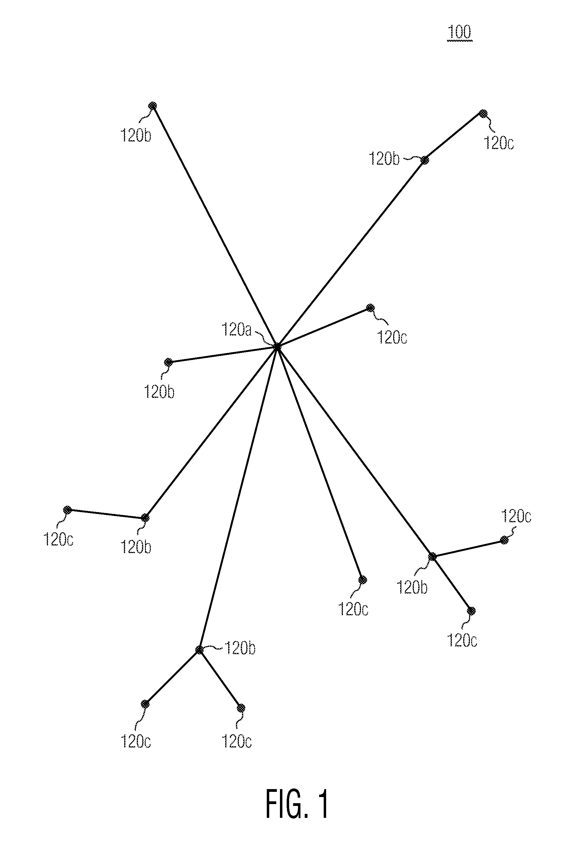
[0006]In contrast, End Device 120c includes just enough functionality to communicate with its “parent node”—which may be either a Router 120b or PAN Coordinator 120a. End Device 120c cannot directly pass messages between two other wireless devices 120. Accordingly, End Device 120c requires the least amount of memory and therefore in general can be manufactured at a lower cost than PAN Coordinator 120a or Router 120b.

Problems solved by technology

Other devices (e.g., so-called “WiFi” devices) also operate in the 2.4 GHz band, and WiFi traffic can interfere with ZigBee traffic.
For example, some interfering devices may transmit data in an intermittent fashion, perhaps with a low duty cycle.
In that case, the energy detection scan described above can lead to misleading results.
At the outset, if the energy detection scan is performed during a time period when an intermittently-interfering device is not transmitting, the energy value may be very low, indicating only the presence of background noise and not recognizing the presence of an intermittent interferer.
However in that case, since the energy value produced in an energy detection scan reflects only the maximum energy detected over the scan period, it is not possible to know how much of the time (if any) the received power level may actually be much less than the maximum energy level.
That is, if the energy detection scan is performed during a scan period when an intermittently-interfering device happens to be transmitting, the maximum energy may be very high, inaccurately indicating a total unavailability for the communication channel.
So, no matter how the scan period may be adjusted, there is a problem in appropriately characterizing communication channels by using energy values each corresponding to a maximum energy detected in a single energy detection scan.
Accordingly, interference in a communication channel that might make the communication channel unsuitable for communication by one wireless device, might not present a major problem for communication by another wireless device with different data communication requirements.
In general, a simple list of energy values for each communication channel corresponding to a maximum energy detected in a single energy detection scan does not provide a robust data set that facilitates optimal decisions for selecting communication channels.
Furthermore, although the problems described above have been illustrated with respect to details of a wireless device operating in a ZigBee PAN, in general problems may occur in other communication networks when only a single energy value is used to try to characterize the availability of a communication channel, even in networks where the energy value is not a maximum detected energy or is obtained from a single measurement rather than from a scan.

Method used


Image

  • Gathering and reporting data concerning communication channel conditions for a wireless device in a wireless network
  • Gathering and reporting data concerning communication channel conditions for a wireless device in a wireless network
  • Gathering and reporting data concerning communication channel conditions for a wireless device in a wireless network

Examples


second embodiment

[0078]Table 6 shows a payload format of a network environment status message from a wireless device. In the embodiment of Table 6, the payload includes a plurality of cost values assigned by wireless device 200 each indicating an estimated availability of communications using the corresponding communication channel, as discussed in greater detail above.

[0079]

TABLE 6Octets: 141VariableStatusScannedScannedSet of cost numbers eachChannelschannelsindicating an estimatedlist countavailability ofcommunications usingthe correspondingcommunication channel

third embodiment

[0080]Table 7 shows a payload format of a network environment status message from a wireless device. For additional flexibility, a wireless device and a PAN Coordinator, for example, may have a table of predefined metrics which assigns an identifier to each of the predefined metrics. In that case, the wireless device may utilize the payload format illustrated in Table 6, which includes a field to provide an identifier of the metric that is being reported.

[0081]

TABLE 7Octets: 14111VariableStatusScannedScannedInformation typeLengthSet of values (eg:channelschannels(eg: indicatesminimum valueslist countminimum valuesreceived from Nincluded)energy scans)

fourth embodiment

[0082]Table 8 shows a payload format of a network environment status message from a wireless device. The payload format of Table 8 includes fields for a wireless device to indicate a plurality of metric types that are being reported, together with their corresponding field lengths.

[0083]

TABLE 8Octets: 14111Variable11VariableStatusScannedScannedInformationLengthSet ofInformationLengthSet ofchannelschannelstype 11valuestype 22valueslist count12


PUM


Abstract

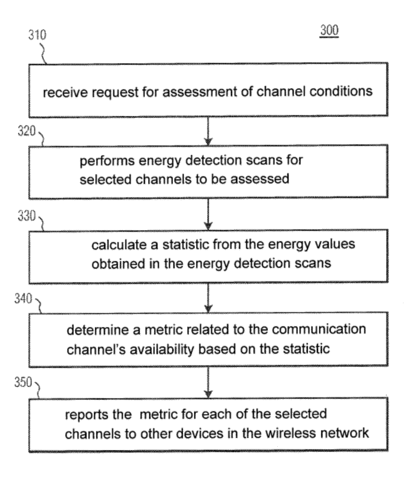
A device for wireless communication with at least one node in a wireless network is configured to obtain statistical data regarding one or more selected communication channels over which the device is adapted to communicate. The, device is further configured to report to at least one other device at least one metric related to an availability of each of the one or more selected communications channels for communications.

Description

TECHNICAL FIELD[0001]This invention pertains to wireless devices and wireless networks, and more specifically to gathering data about the conditions of communication channels for a wireless device, and reporting the data to a wireless network.BACKGROUND AND SUMMARY[0002]Wireless networks are increasingly commonly employed to provide enhanced capabilities for a variety of devices. One category of wireless networks is a wireless Personal Area Network (PAN). One suitable format for communications in a wireless PAN is described by the ZigBee Specification for low cost, low power wireless radio links, as defined by the ZigBee Alliance. ZigBee wireless PANs are especially suitable for use, for example, in home automation networks for controlling lights, security systems, fire alarms, heating-ventilation-and-air-conditioning (HVAC) systems, etc.[0003]FIG. 1 shows one exemplary embodiment of a wireless network 100 including a plurality of wireless devices 120. Wireless network 100 may be a ...

Claims


Application Information

Patent Timeline
Patent Type & Authority Patents(United States)
IPC IPC(8): G01R31/08H04W72/02H04W72/04H04W72/08
CPCH04W72/085H04W72/02H04W72/0406H04W72/20H04W72/542H04W24/10H04W88/02
Inventor RUDLAND, PHILIP ANDREWBENJES, IMMO
Owner SIGNIFY HLDG BV
Why Eureka
Eureka Blog
Learn More