
Magneto-encephalography device

a magnetic field and electrode technology, applied in the direction of magnetic field magnitude/direction, magnetic field measurement using magneto-optic devices, etc., can solve the problems of not being able to place directly on the skull, neuro-magnetic signals are not as clear, and the sensor cannot be placed directly on the skull

Active Publication Date: 2019-12-03
ROYAL MELBOURNE INST OF TECH
View PDF20 Cites 4 Cited by
  • Summary
  • Abstract
  • Description
  • Claims
  • Application Information

AI Technical Summary

Benefits of technology

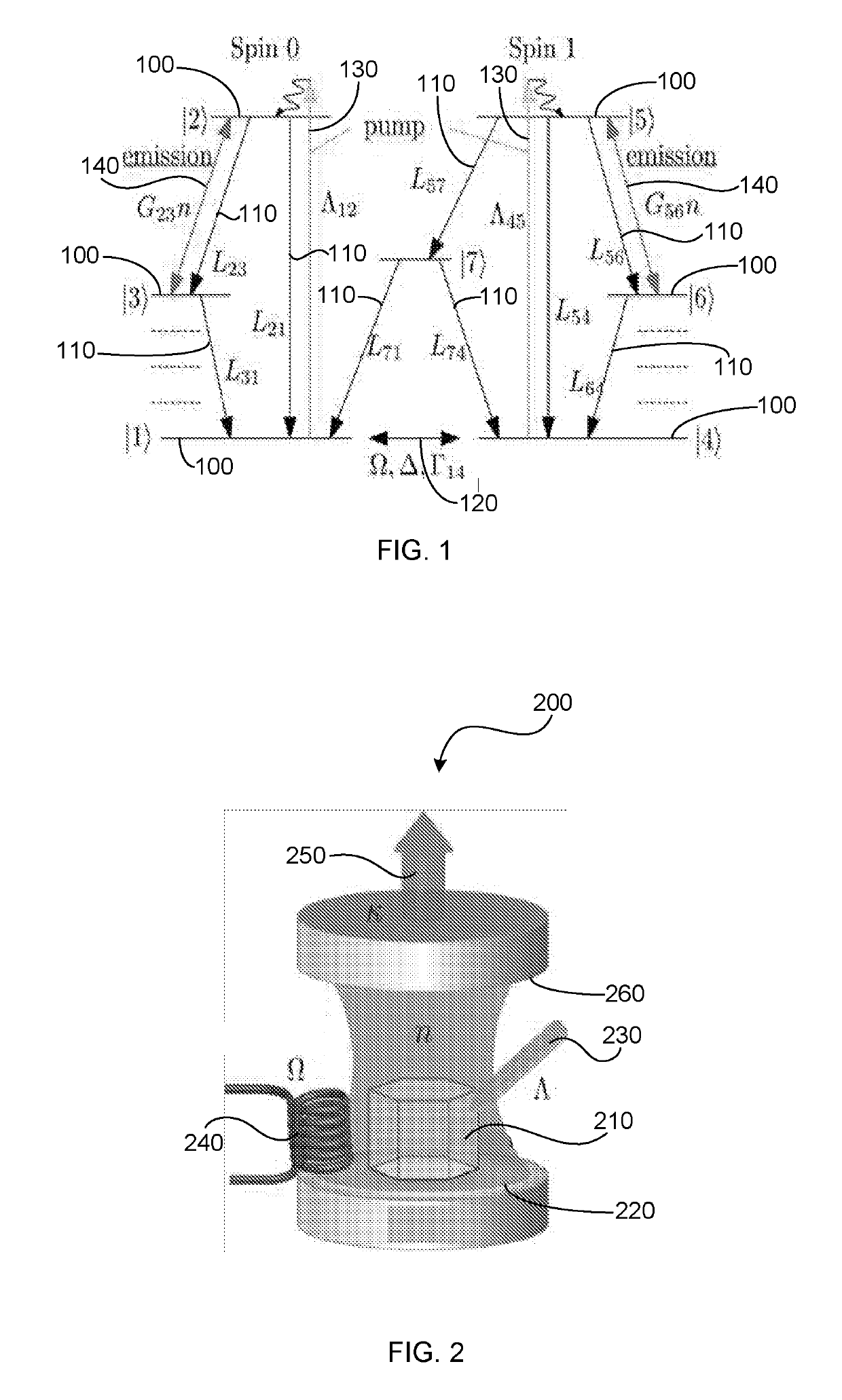
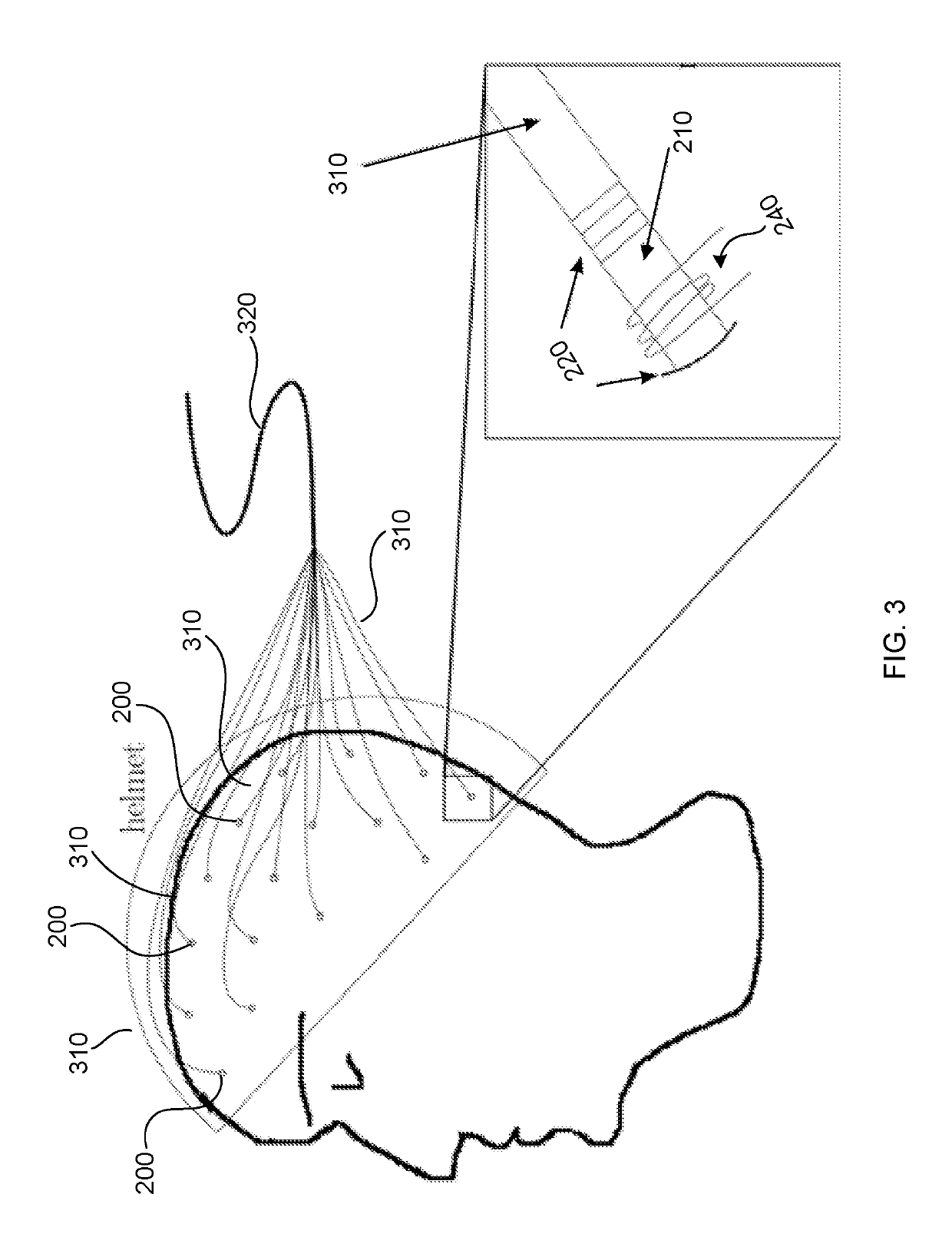
The present invention is about a magneto-encephalography device that uses laser threshold magnetometers to measure magnetic fields in a subject's brain. These magnetometers consist of a laser medium with a laser threshold, a laser pump, and a radio-frequency drive that induces transitions between different states of the laser medium, resulting in different laser thresholds based on the magnetic field. The magnetometers are placed directly on the subject's head, and can measure the magnetic field proximal to the location of the magnetometer. The intensity of the laser output is proportional to the magnetic field and can be mapped in three dimensions using triangulation techniques. The laser output is guided into an optical fibre, which sends it to a light sensor. The laser threshold magnetometers are pumped through the optical fibre. Overall, this device provides a non-invasive and accurate measure of brain activity.

Problems solved by technology

Whilst SQUID sensors are highly sensitive, a considerable drawback to their application is that SQUID sensors require cryogenic cooling.
Moreover, since SQUID sensors operate at cryogenic temperatures (typically below 10K), they cannot be placed directly on the skull, without some form of temperature insulation.
As a result, of this separation, the neuro-magnetic signals are not as clear as they could be if the sensors were able to be positioned directly on the skull.
Moreover, cryogenic cooling is typically performed with liquid helium which is both an expensive and a finite resource, which is projected to be exhausted in 20 years.

Method used


Image

  • Magneto-encephalography device
  • Magneto-encephalography device

Examples


Embodiment Construction

[0020]The present invention is directed to a magneto-encephalography device which is based on one or more laser threshold sensors. The construction and operation of a laser threshold magnetometer is described below. Additional detail is provided in co-pending U.S. patent application Ser. No. 14 / 879,769 filed on 9 Oct. 2015 to RMIT University.

[0021]A laser consists of at least a laser medium, a cavity and a laser pump, which is typically a light source, typically in or close to the visible range or electrical pumping, which is applied to the laser medium. The laser pump lifts single atoms or single colour centres of the laser medium into an energetically higher lying excited state. From this excited state the laser medium returns to an energetically lower lying state; the energy difference is emitted as light (a photon). The photon is created with a wavelength and energy corresponding to that energy difference of the two states. The lower lying energy state has multiple states slight...


PUM


Abstract

A magneto-encephalography device including a plurality of laser threshold magnetometers for measuring a magnetic field is provided. Each laser threshold magnetometer includes an optical cavity, a laser medium which together with the optical cavity has a laser threshold; a laser pump; and a radio-frequency (RF) drive applied to the laser medium at or around a particular resonance frequency which varies depending on the magnetic field, such that depending on the value of the physical parameter, the RF drive induces transitions between at least two states of the laser medium, each state causing a different laser threshold in an intensity of a laser output, wherein the intensity of the laser output provides a measurement of the magnitude of the magnetic field; wherein the laser threshold magnetometers are configured to be placed on a head of a subject to be monitored.

Description

CROSS-REFERENCE TO RELATED APPLICATIONS[0001]The application claims priority to PCT / AU2016 / 050667, which was filed on Jul. 27 2016, which claims priority to AU 2015903002, which was filed on Jul. 28, 2015, AU 2015230816, which was filed on Sep. 25, 2015, and U.S. application Ser. No. 14 / 879,769, which was filed on Oct. 9, 2015, the contents of each of which is incorporated by reference in their entirety.TECHNICAL FIELD[0002]The present invention relates to a magneto-encephalography device for measuring and monitoring the magnetic fields produced by brain activity in a subject. More particularly, the magneto-encephalography device is based on one or more laser threshold sensors.BACKGROUND OF INVENTION[0003]Magneto-encephalography (MEG) is a non-invasive neuroimaging technique for mapping brain activity. Recording probes are placed on the surface of the skull to record activity occurring on the surface of the brain. Using triangulation techniques, brain activity detected by the probes...

Claims


Application Information

Patent Timeline
Patent Type & Authority Patents(United States)
IPC IPC(8): G01R33/032
CPCG01R33/032
Inventor JESKE, JANGREENTREE, ANDREWCOLE, JARED
Owner ROYAL MELBOURNE INST OF TECH
Learn More