Connector system for lighting assembly

a technology of connecting system and lighting assembly, which is applied in the direction of coupling device connection, lighting support device, lighting and heating apparatus, etc., can solve the problems of mercury exposure, incandescent light bulbs, and inefficient lighting,

Active Publication Date: 2019-11-26
DVA HLDG LLC
View PDF235 Cites 1 Cited by
  • Summary
  • Abstract
  • Description
  • Claims
  • Application Information

AI Technical Summary

Problems solved by technology

Incandescent light bulbs, however, are very inefficient, as a high percentage of energy input is lost as heat.
While the heat generated by fluorescent lamps is much less than its incandescent counterparts, energy is still lost in generating the UV light and converting UV light into visible light.
If the lamp breaks, exposure to mercury can occur.
Some fluorescent lights flicker and the quality of the fluorescent light tends to be a harsh white due to the lack of a broad band of frequencies.
Most fluorescent lights are not compatible with dimmers.
The heat sink itself, as well as the printed circuit LED boards and other electrical components within the linear LED tube assembly, present a safety hazard without proper electrical grounding.
This is because the line voltage or voltage input to the LED boards could be applied to the heat sink in the event of a short circuit, for example, if the insulation between the LEDs and/or internal driver circuitry and the heat sink is inadequate or deteriorates during use.
This could lead to other components within the assembly overheating and creating a fire hazard.
It also creates an electrical shock hazard should the user come into physical contact with the heat sink when inspecting the installed lamp.
The electrical components within the lamp, such as LEDs and driver circuits, are also susceptible of being damaged in the event of a power surge.
The exposed pins on the ends of the linear LED tube are susceptible to damage during distribution and installation.
Often one or more of the pins are misaligned during this process so that electrical connection is not established.
The same misalignment may cause...

Method used


Image

  • Connector system for lighting assembly
  • Connector system for lighting assembly
  • Connector system for lighting assembly

Examples


Embodiment Construction

[0044]For the purposes of promoting an understanding of the principles of the invention, reference will now be made to the embodiments illustrated in the drawings and specific language will be used to describe the same. It will nevertheless be understood that no limitation of the scope of the invention is thereby intended. Any such alterations and further modifications in the illustrated devices, and such further applications of the principles of the invention as illustrated herein are contemplated as would normally occur to one skilled in the art to which the invention relates.

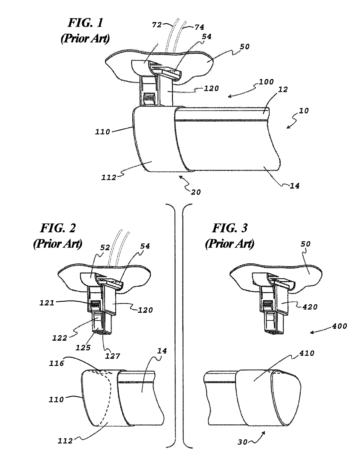
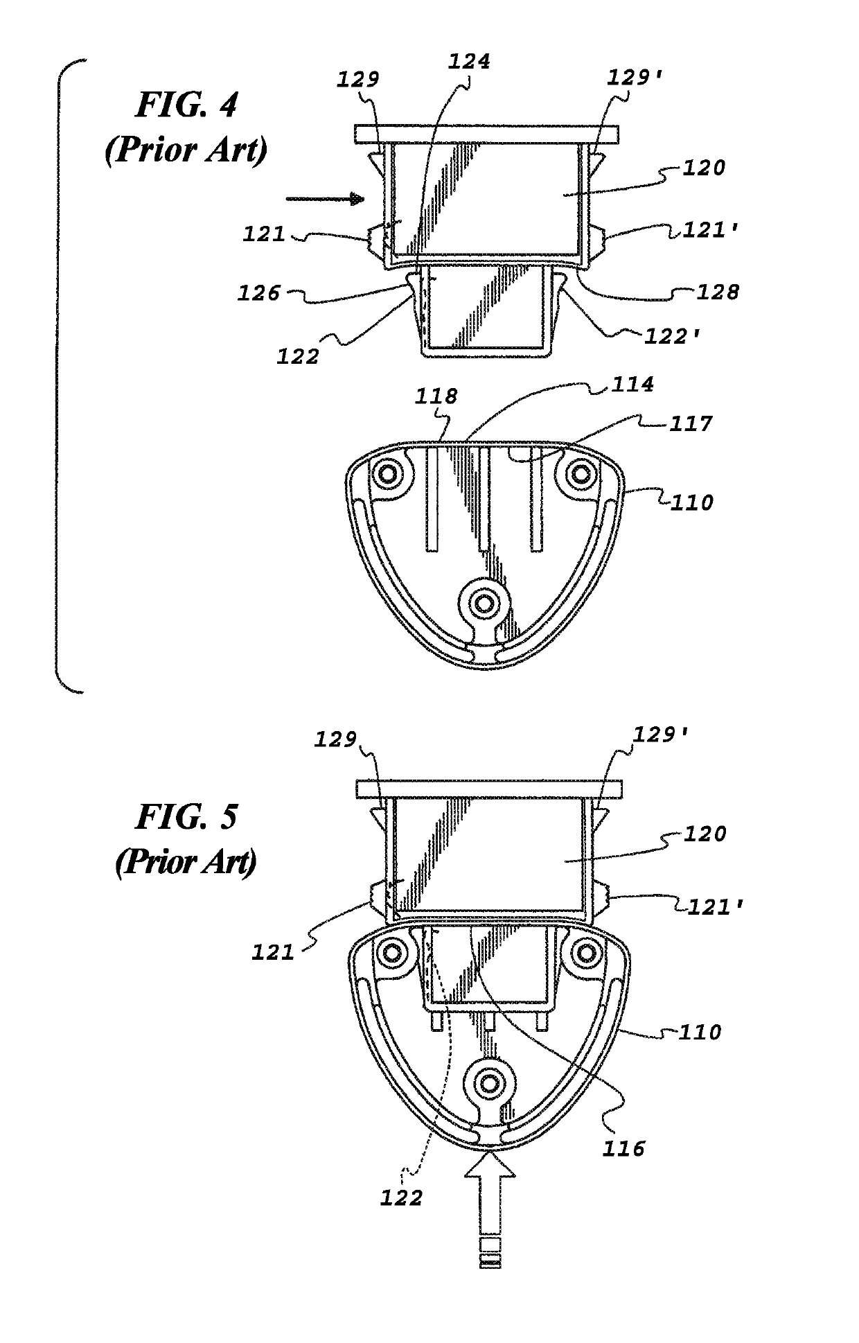
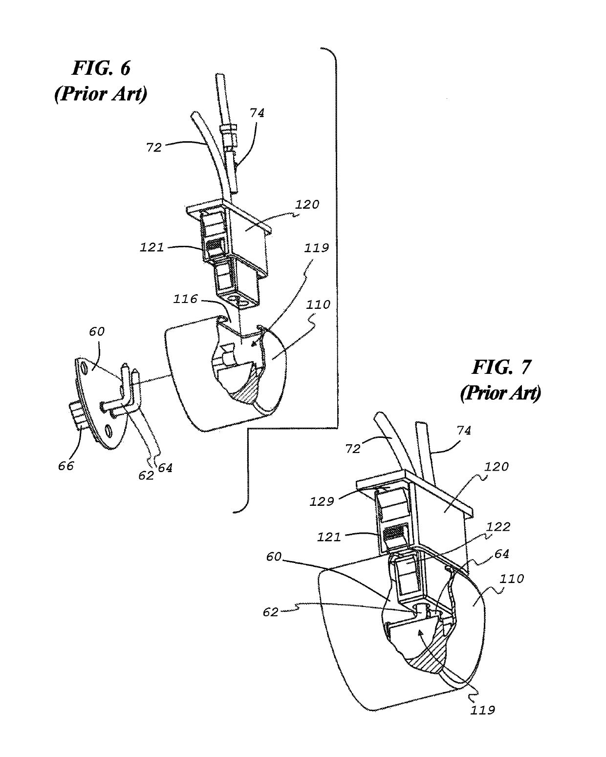
[0045]There is a need for an improved lamp holder and connector system that address all safety issues and provides a grounded LED lighting system in the linear tube format that is widely deployed throughout the lighting industry. As used herein, the terms “LED tube lamp” and “linear LED lamp” and similar variants are used interchangeably to describe LED lamps having at least one LED board mounted on an extern...


PUM


Abstract

A support connector for maintaining an end of a linear LED lamp in an operative state on a support. The support connector comprises a nonconductive housing comprising a first portion including a mounting base at one end of the first portion configured to couple the support connector to the support. A second portion extends from the opposite end of the first portion and is configured to be insertable within an opening of a first end cap assembly of the linear LED lamp. First and second power electrical terminals are disposed within first and second receptacles of the support connector, and a grounding electrical terminal is disposed within a third receptacle, and the grounding electrical terminal is electrically isolated from the first and second power terminals. The first and second power electrical terminals mate with first and second conductive power pins of the end cap assembly, and the grounding electrical terminal is configured to mate with a grounding pin of the end cap assembly as the first end cap assembly is moved relative to the support connector from a position fully separated from the support connector in a path that is transverse to the length of the body into an engaged position.

Description

CROSS-REFERENCE TO RELATED APPLICATIONS[0001]This application is a continuation application of U.S. patent application Ser. No. 15 / 401,537, entitled “Connector System For Lighting Assembly” and filed Jan. 9, 2017, which claims the benefit of U.S. Provisional Patent Application No. 62 / 276,075, entitled “Connector System For Lighting Assembly” and filed Jan. 7, 2016, and U.S. Provisional Patent Application No. 62 / 422,521, entitled “Connector System For Lighting Assembly” and filed Nov. 15, 2016, which are hereby incorporated by reference in their entirety herein.FIELD[0002]This invention relates to lighting and, more particularly, to light emitting diode (LED) illumination as well as tubular lighting assemblies.BACKGROUND[0003]Over the years various types of illuminating assemblies and devices have been developed for indoor and / or outdoor illumination, such as torches, oil lamps, gas lamps, lanterns, incandescent bulbs, neon signs, fluorescent bulbs, halogen lights, and light emitting...

Claims


Application Information

Patent Timeline
IPC IPC(8): F21V23/06F21V21/002F21V23/02F21V23/00F21V15/015F21V19/00F21V29/74H01R33/08F21K9/20F21K9/278F21K9/272H01R13/627F21V29/89F21V3/02F21K9/66F21Y103/10F21Y115/10
CPCH01R13/6273F21K9/20F21V23/001F21V29/74F21V23/02F21K9/272F21V15/015F21V21/002H01R33/0845F21K9/278F21V23/06F21V19/0085F21V29/89F21V3/02F21Y2115/10F21K9/66F21Y2103/10G01M3/08G01M3/083
Inventor MAY, MICHAEL W.
Owner DVA HLDG LLC
Why Eureka
Try Eureka