
Fabrication and operation of multi-function flexible radiation detection systems

a radiation detection system and multi-functional technology, applied in the direction of measurement with semiconductor devices, instruments, radiation controlled devices, etc., can solve the problems of difficult automation of gas detector manufacturing, weak and limited detector types, and gas detectors that cannot differentiate between the energies of incident radiation, etc., to achieve the effect of higher signal

Active Publication Date: 2019-11-19
MPOWER TECH
View PDF59 Cites 5 Cited by
  • Summary
  • Abstract
  • Description
  • Claims
  • Application Information

AI Technical Summary

Benefits of technology

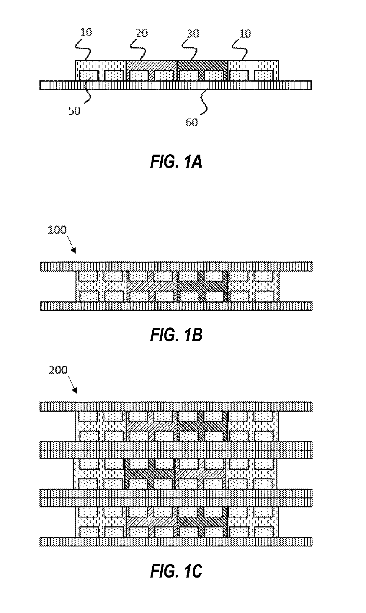
The radiation detector described in this patent can detect the direction and track the movement of particles in incident radiation. It uses multiple layers of detectors that generate signals for each particle, resulting in a higher signal. The detector has integrated circuitry that performs various functions on the signals, such as pre-conditioning, amplification, filtering, and processing. The integrated circuitry is embedded with each sensor and can perform these functions without transmitting the signals to an edge circuit. The detector also includes a flexing conversion layer that does not substantially reduce its functionality.

Problems solved by technology

Typically, gas detectors cannot differentiate between the energies of the incident radiation.
Each of these detector types have weaknesses and limitations.
It is difficult to automate the manufacturing of gas detectors, which keeps the detector prices high.
Scintillation detectors have good stopping power, but are very heavy being large detectors, difficult to handle, cannot take rough handling, and are expensive.
CdTe detectors simply cannot be made in large size; if a large detector active size is required, one must use arrays of the detectors which is both expensive and requires duplication of the electronics adding to the complications and expense.
HPGe detectors have the ultimate energy resolution but require cooling mechanisms (liquid nitrogen dewars or mechanical cooling systems), which makes them both expensive and bulky.
They also cannot be made arbitrarily large.
Furthermore, many of these systems are bulky, require integration and careful handling of fragile and / or hazardous materials and some systems also require cryogenic cooling to achieve the desired functionality.

Method used


Image

  • Fabrication and operation of multi-function flexible radiation detection systems
  • Fabrication and operation of multi-function flexible radiation detection systems
  • Fabrication and operation of multi-function flexible radiation detection systems

Examples


Embodiment Construction

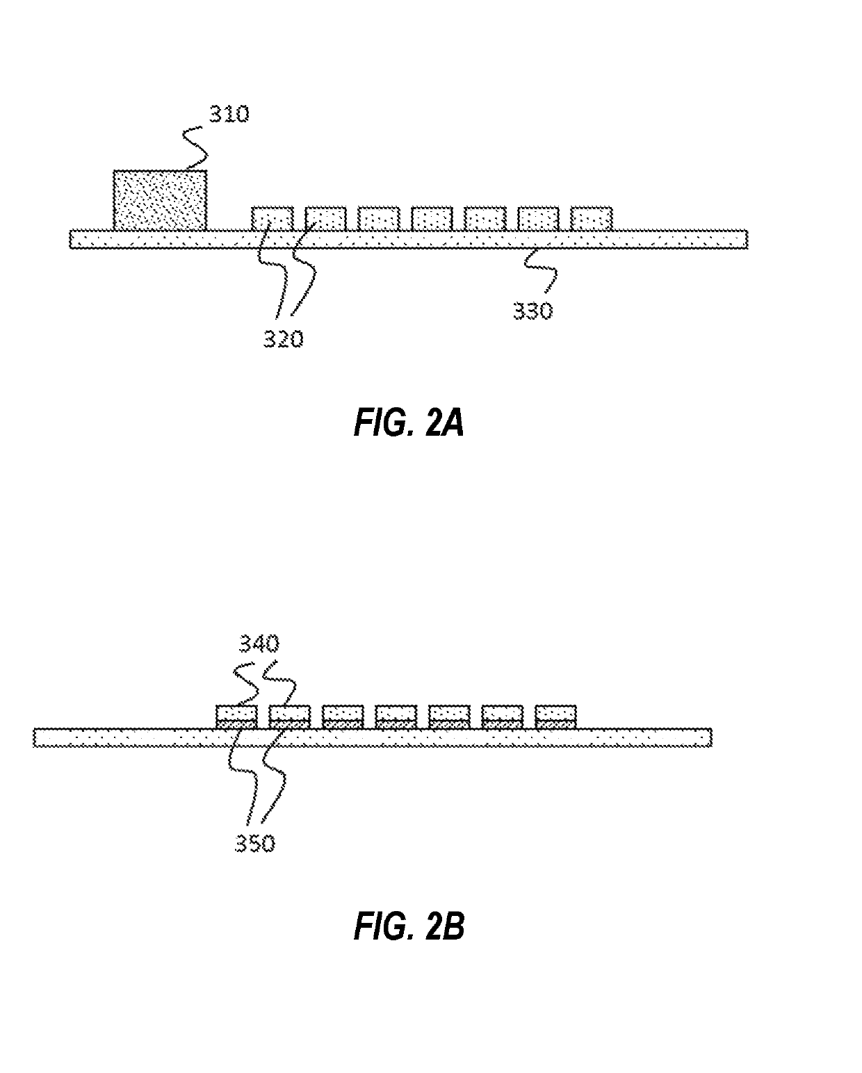
[0020]Embodiments of the present invention provide significant improvements in radiation detection through the use of micro-scale, individually mechanically separated semiconductor detector elements and electronic circuitry that are preferably interconnected on an integrated mechanically flexible substrate, which are preferably further functionalized with the necessary conversion and shielding materials. In previous attempts at integration of conversion materials with semiconductor detectors, the fragile nature of the semiconductor layers and the challenges in integration of the desired conversion materials have limited the functionality and utility of such detectors.

[0021]The individual detector elements (e.g. p-n junctions) and electronic circuitry to pre-condition and process the generated signals are preferably manufactured using standard silicon semiconductor processing tools and materials. Desired conversion materials are then preferably spun-on in liquid or gel form, evaporat...


PUM


Abstract

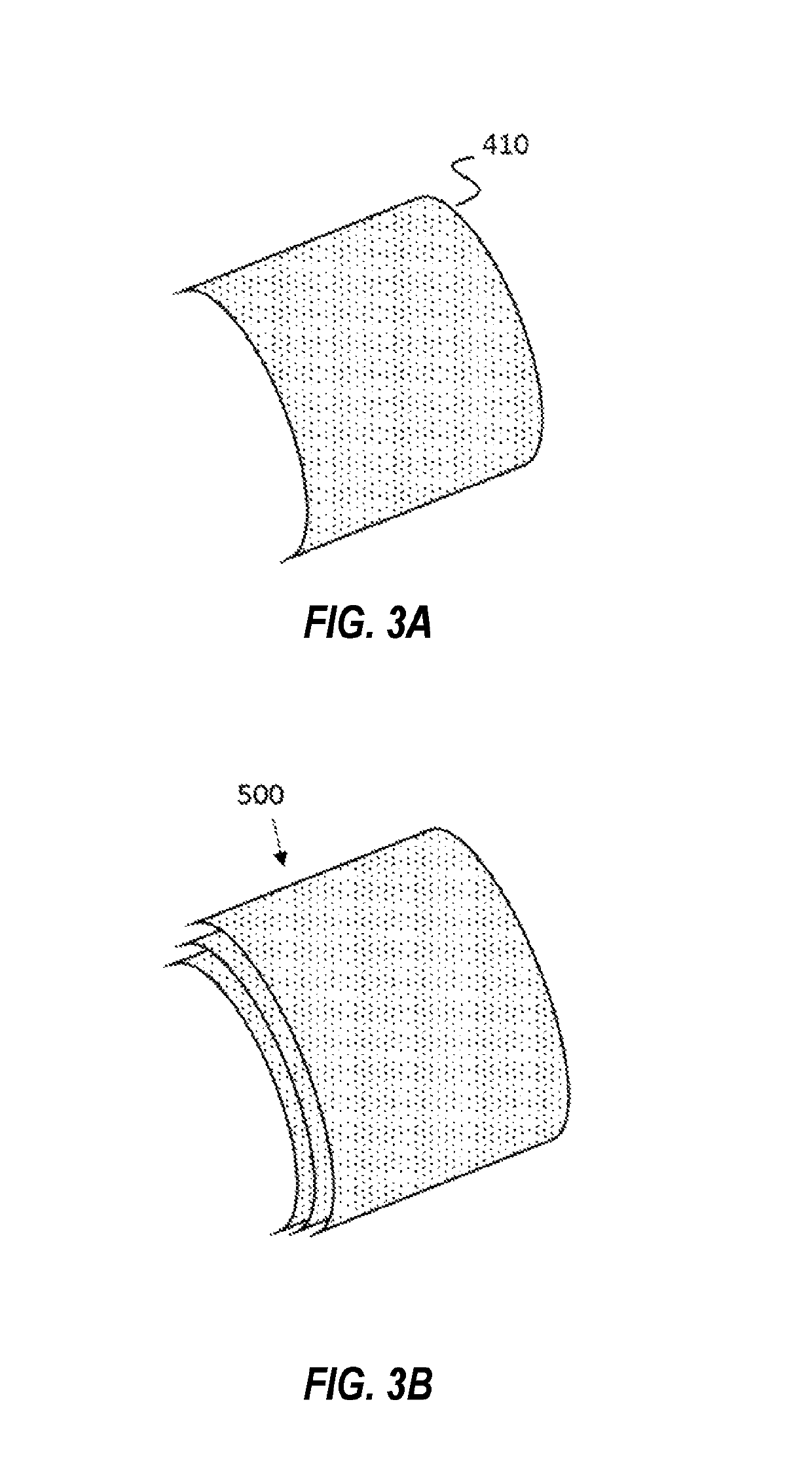
Curved, flexible arrays of radiation detectors are formed by using standard silicon semiconductor processing materials and techniques and additional functionalization through integration of conversion and shielding materials. The resulting flexible arrays can be handled, integrated, further functionalized and deployed for a wide variety of applications where conventional sensors do not provide the desired functionality, form factors and / or reliability. The arrays can be stacked and include multiple types and thicknesses of conversion layers, enabling the detector to simultaneously detect multiple radiation types, and perform complex, simultaneous functions such as energy discrimination, spectroscopy, directionality detection, and particle trajectory tracking of incident radiation.

Description

CROSS-REFERENCE TO RELATED APPLICATIONS[0001]This application claims priority to and the benefit of filing of U.S. Provisional Patent Application Ser. No. 62 / 278,103, entitled “ FABRICATION AND OPERATION OF MULTI-FUNCTION FLEXIBLE RADIATION DETECTION SYSTEMS”, filed on Jan. 13, 2016, the specifications and claims of which are incorporated herein by reference.BACKGROUND OF THE INVENTION[0002]Field of the Invention (Technical Field)[0003]The present invention is related to fabrication, assembly, feature integration and operation of low cost, flexible, high performance radiation detectors based on thin, singulated, flexible semiconductor devices and necessary functionalization materials.[0004]Background Art[0005]Note that the following discussion may refer to a number of publications and references. Discussion of such publications herein is given for more complete background of the scientific principles and is not to be construed as an admission that such publications are prior art for...

Claims


Application Information

Patent Timeline
Patent Type & Authority Patents(United States)
IPC IPC(8): G01T1/24H01L27/146G01T3/08
CPCG01T3/08H01L27/14659G01T1/241G01T7/00G01T1/24G01T1/20181
Inventor OKANDAN, MURATKOSKELO, MARKKU JUHANI
Owner MPOWER TECH
Learn More