Multiplexer, transmission apparatus, and reception apparatus
a transmission apparatus and multi-channel technology, applied in the field of multi-channel transmission apparatus and reception apparatus, can solve the problems of difficult to ensure low-loss characteristics in the pass band of the multiplexer, and the difficulty of achieving impedance matching for a plurality of filter elements using only the above-mentioned impedance matching circuit, so as to achieve the effect of significantly reducing or preventing the loss of insertion in the pass band of each filter elemen
- Summary
- Abstract
- Description
- Claims
- Application Information
AI Technical Summary
Benefits of technology
Problems solved by technology
Method used
Image
Examples
first preferred embodiment
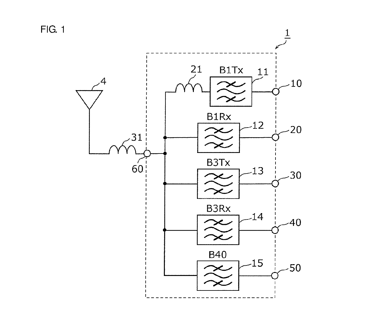
[0066]FIG. 1 is a circuit diagram of the multiplexer 1 according to a first preferred embodiment of the present invention. As shown in FIG. 1, the multiplexer 1 includes transmission filters 11 and 13, reception filters 12 and 14, a transmission and reception filter 15, an inductance element 21, a common terminal 60, transmission input terminals 10 and 30, reception output terminals 20 and 40, and an input and output terminal 50. The multiplexer 1 is connected to an antenna element 4 with an inductance element 31 therebetween, the inductance element 31 being connected in series to the common terminal 60 and the antenna element 4. The inductance element 31 defines and functions as an impedance matching element.
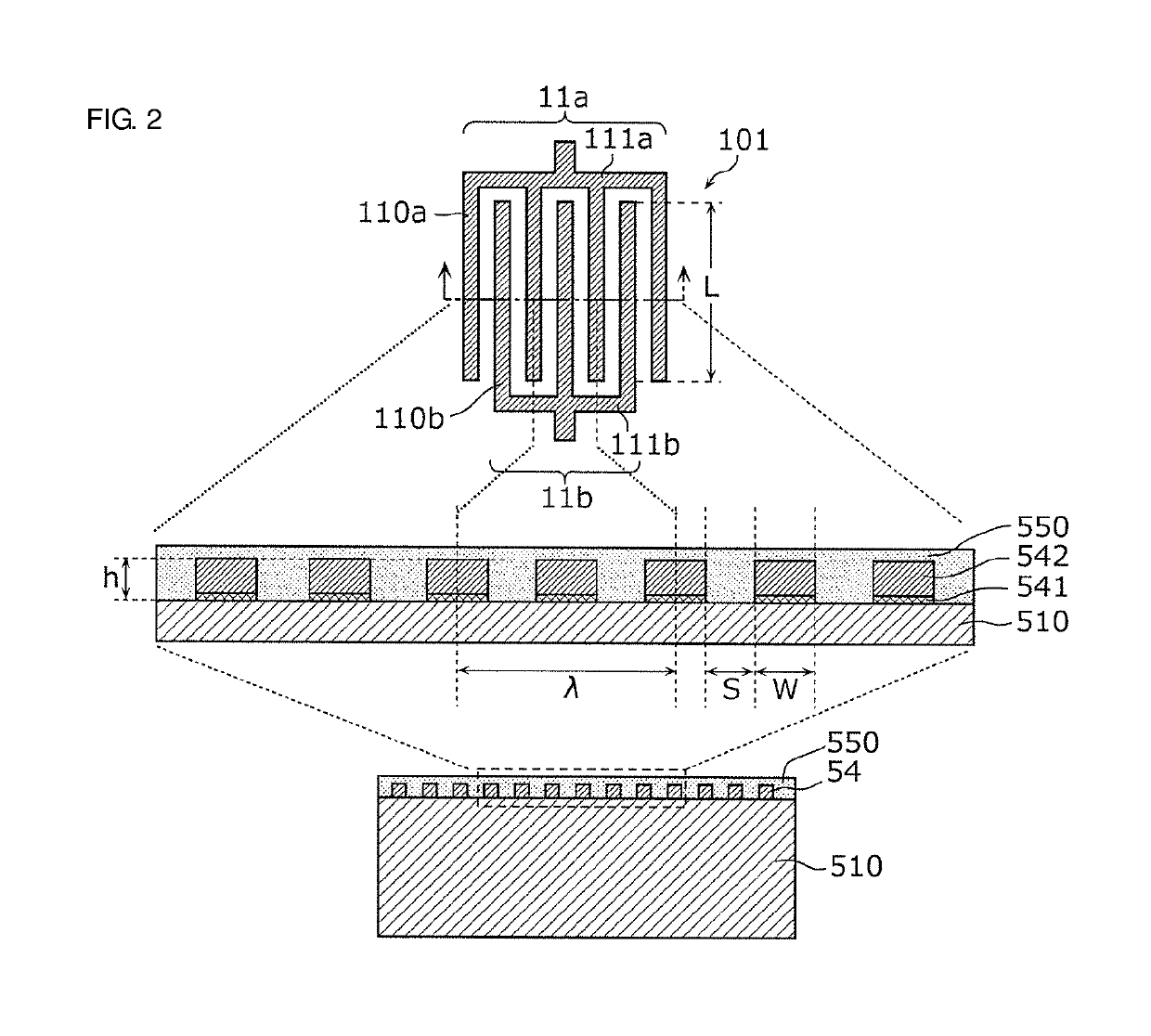
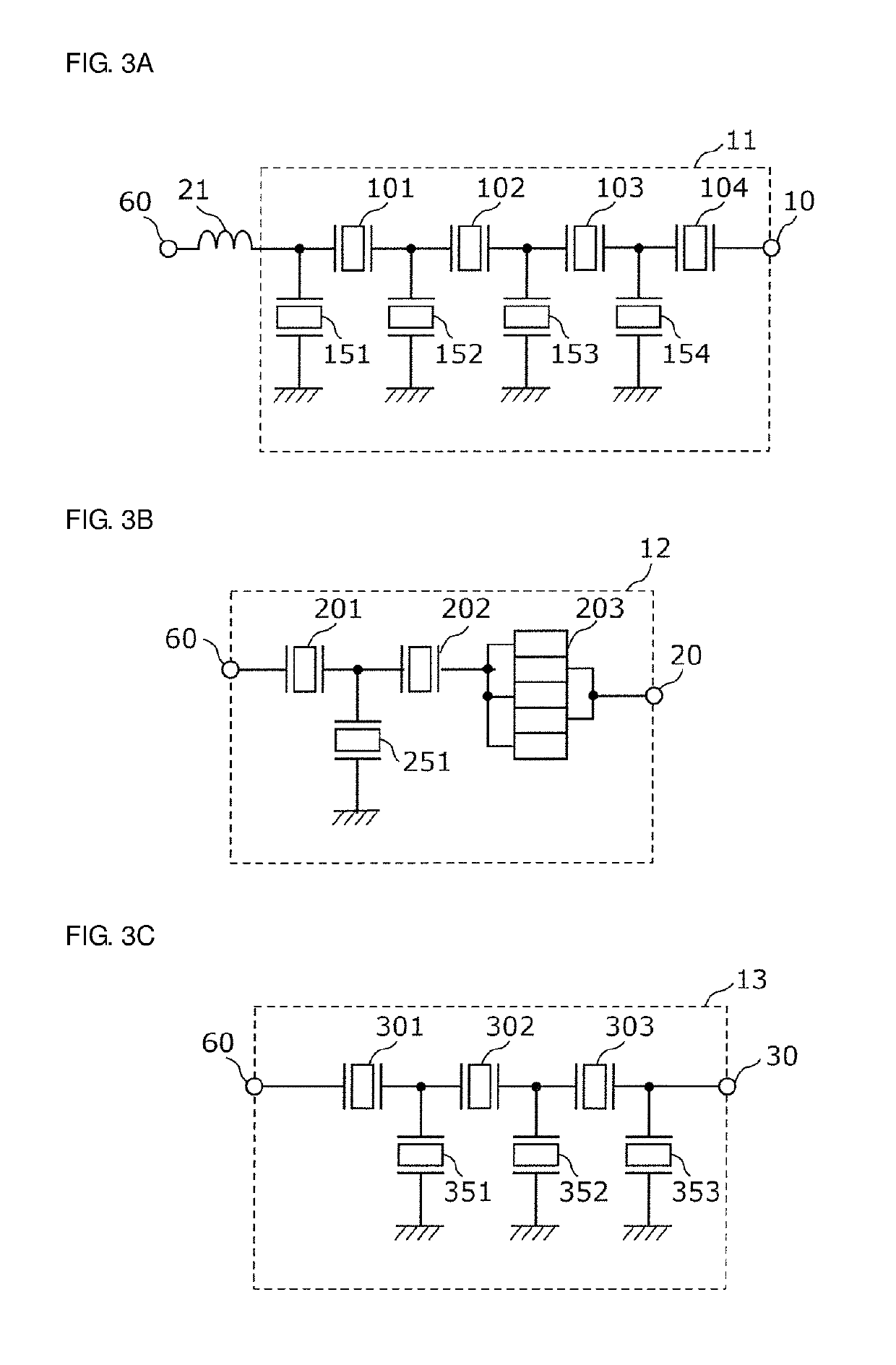
[0067]The transmission filter 11 is a band pass filter which inputs a transmission signal generated at a transmission circuit (for example, an RFIC or the like) via the transmission input terminal 10, performs filtering with the transmission pass band (for example, from about 1...
second preferred embodiment
[0137]As illustrated in FIG. 12, a multiplexer 1A according to a second preferred embodiment of the present invention includes the same configuration as that of the first preferred embodiment, but a capacitance element 22 is preferably connected in parallel between a reference terminal (for example, ground) and a connection point of the inductance element 21 and the transmission filter 11. The second preferred embodiment provides advantages similar to those of the first preferred embodiment.
[0138]FIG. 13 is a diagram showing an LC series resonant circuit including an inductor element, a capacitor element, and a filter element according to the second preferred embodiment of the present invention. As shown in FIG. 13, for example, in the case where the inductance element 21 is connected in series between the transmission filter 11 and the common terminal 60 and the capacitance element 22 is connected in parallel between a reference terminal and the connection point of the first induct...
third preferred embodiment
[0140]As illustrated in FIG. 14, a multiplexer 1B according to a third preferred embodiment of the present invention includes the same configuration as that of the first preferred embodiment, but a second inductance element 23 is preferably connected in series between the inductance element 21 and the transmission filter 11. The third preferred embodiment provides advantages similar to those of the first preferred embodiment.
[0141]FIG. 15 is a diagram showing an LC series resonant circuit including a first inductor element, a second inductor element, and a filter element according to the third preferred embodiment of the present invention. As shown in FIG. 15, for example, in the case where the first inductance element 21 and the second inductance element 23 are connected in series between the transmission filter 11 and the common terminal 60, LC series resonance is generated at a path from the common terminal 60 to a reference terminal (for example, ground) by an inductive componen...
PUM
 Abstract
Description
Claims
Application Information
 - R&D
- Intellectual Property
- Life Sciences
- Materials
- Tech Scout
- Unparalleled Data Quality
- Higher Quality Content
- 60% Fewer Hallucinations
Browse by: Latest US Patents, China's latest patents, Technical Efficacy Thesaurus, Application Domain, Technology Topic, Popular Technical Reports.
© 2025 PatSnap. All rights reserved.Legal|Privacy policy|Modern Slavery Act Transparency Statement|Sitemap|About US| Contact US: help@patsnap.com


