
Device and method for wiring a battery management system

a battery management system and device technology, applied in the direction of charging management, charging equalisation circuit, electric vehicles, etc., can solve problems such as the explosion of batteries, and achieve the effect of reducing the energy consumption of the first energy sour

Inactive Publication Date: 2019-11-12
FRAUNHOFER GESELLSCHAFT ZUR FOERDERUNG DER ANGEWANDTEN FORSCHUNG EV
View PDF38 Cites 0 Cited by
  • Summary
  • Abstract
  • Description
  • Claims
  • Application Information

AI Technical Summary

Benefits of technology

[0015]The present invention makes use of the effect that by means of intelligently disconnecting a battery management system from a first energy source by a first switch unit, no more electrical energy is supplied to the battery management system. Increased self-discharge of the first energy source and / or increased consumption of energy from the first energy source is curbed, which increases energy efficiency. Reduced energy consumption and increased efficiency entail economic advantages and are easy on the environment. This is highly significant in particular with battery supply systems. In addition, relatively long downtimes can be tolerated without regularly testing the first energy source. Mechanical separation (disconnection) of the battery management system from the first energy source is no longer required. This results in improved maintainability of the circuit system. The reliability of the circuit system is further increased in some embodiments in that exhaustive discharge due to self-discharge by the battery management system is prevented in advance in that the battery management system is capable of intelligently switching itself off if it detects a low state of charge of the first energy source.
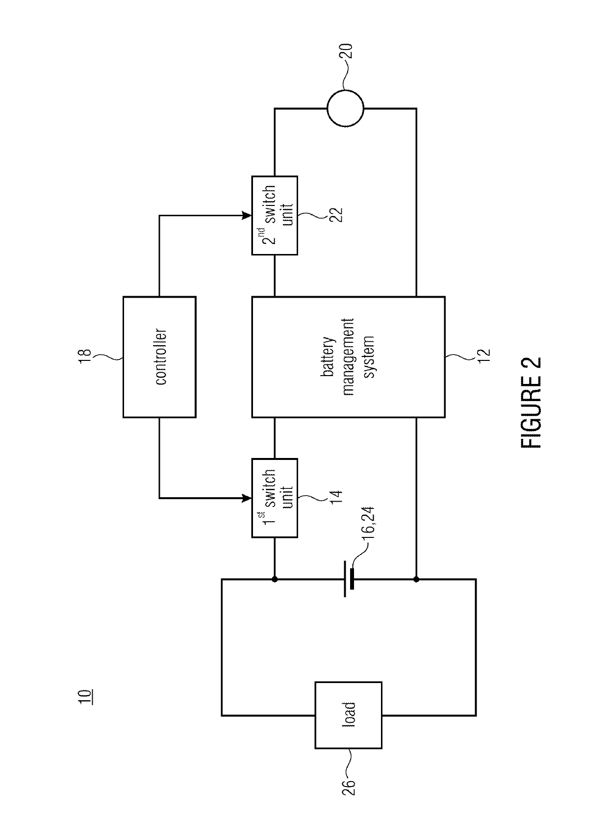
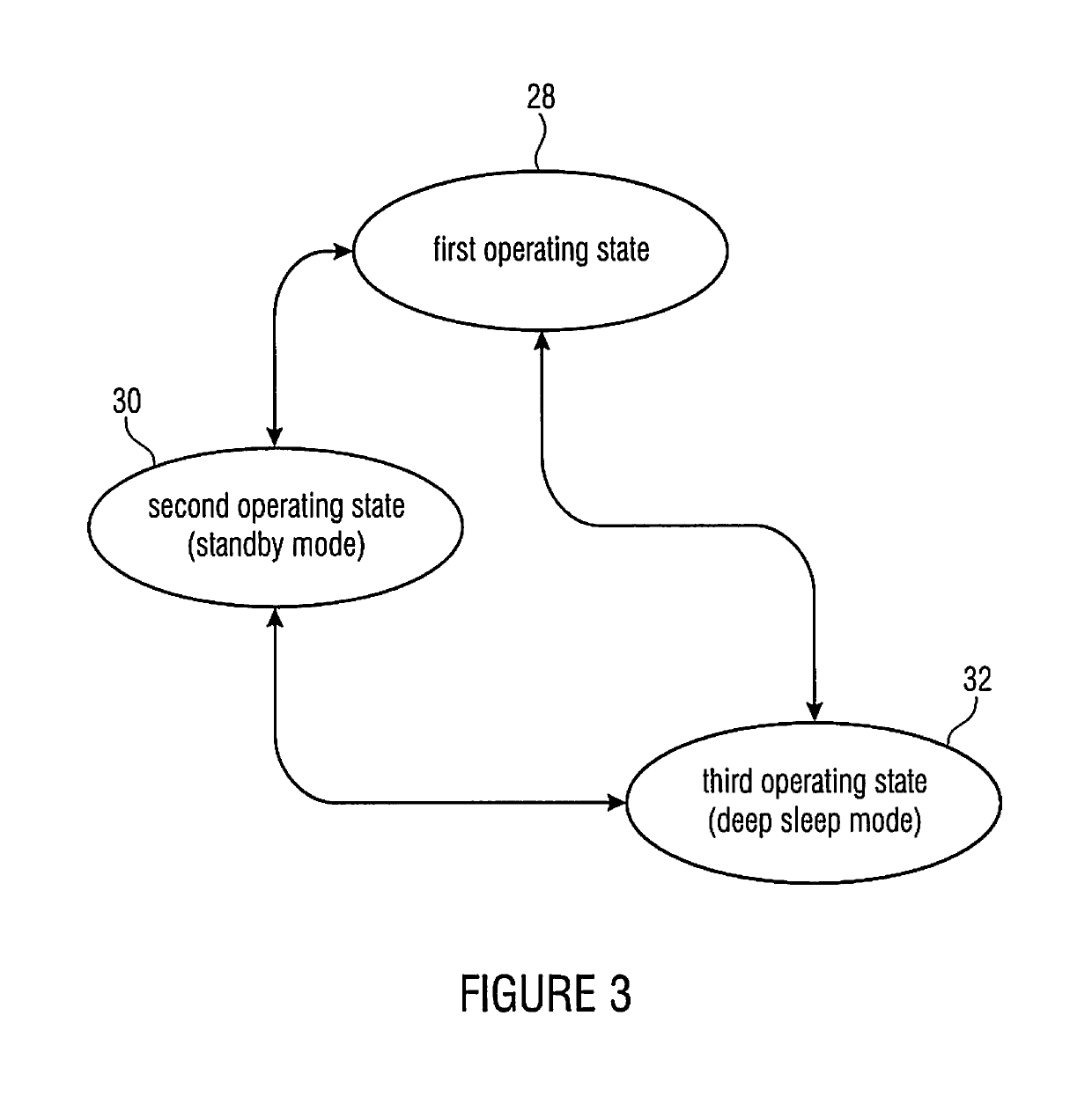
[0024]Moreover, the battery management system may be configured to generate, on account of battery information output by the battery-cell electronics and of monitoring information output by the monitoring unit, control information and to transfer said control information to the controller. For example, the battery management system may be configured to ascertain that no energy is flowing to the first energy source and that, also, no energy is flowing out of the first energy source, and to consequently cause a first operating state of the battery management system to change to a second operating state of the battery management system. The control information is output by the controller and causes the first switch unit and / or the second switch unit to change their respective states. As a result, the operating state of the battery management system is changed. When no energy is flowing to or out of the first energy source, the battery management system will be able to change from a normal operating mode to a standby mode and to thereby reduce the energy consumption of the first energy source.

Problems solved by technology

In the worst case, this may cause a battery cell to explode.
This results in that due to its own energy consumption, a BMS may exhaust a battery system or an individual battery cell.
This may occur particularly when the battery system is not charged for a long time.

Method used


Image

  • Device and method for wiring a battery management system
  • Device and method for wiring a battery management system
  • Device and method for wiring a battery management system

Examples


Embodiment Construction

[0034]In the subsequent description of the embodiments of the invention, elements that are identical or equivalent will be provided with identical reference numerals in the figures, so that their descriptions in the different embodiments are interchangeable.

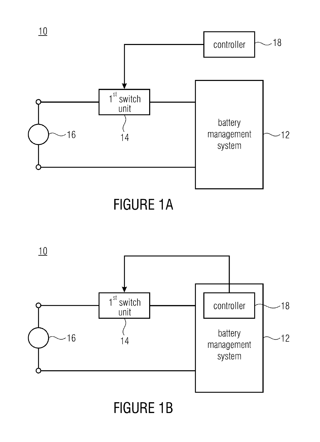
[0035]FIGS. 1a and 1b show schematic representations of first and second embodiments of a circuit system 10. The circuit system 10 in accordance with the first and second embodiments, respectively, each includes a battery management system 12, a first switch unit 14 which in a first state conductively connects a first energy source 16 to the battery management system 12 and disconnects, in a second state, the energy supply of the battery management system 12 from the first energy source 16. In addition, the circuit system 10 includes a controller 18 controlling the first switch unit 14.

[0036]In FIG. 1a, the controller 18 is an external unit with regard to the battery management system 12. However, the controller 18 may also be in...


PUM


Abstract

A circuit system includes a battery management system, a first switch unit and a controller. In a first state, the first switch unit conductively connects a first energy source to the battery management system, and in a second state it interrupts the energy supply of the battery management system from the first energy source. The controller controls the first switch unit.

Description

CROSS-REFERENCE TO RELATED APPLICATIONS[0001]This application is a continuation of copending International Application No. PCT / EP2015 / 054959, filed Mar. 10, 2015, which claims priority from German Application No. 102014204473.1, filed Mar. 11, 2014, which are each incorporated herein in its entirety by this reference thereto.[0002]Embodiments of the present invention relate to a circuit system for wiring a battery management system. Further embodiments relate to a method of wiring a battery management system.BACKGROUND OF THE INVENTION[0003]Management systems, e.g., in the form of electronic circuit boards comprising software that is integrated accordingly, may be used for monitoring, controlling and measuring rechargeable chemical energy storage devices in various fields of application. Said management systems will be referred to below as battery management systems (abbreviation: BMS). One example of a chemical storage device are lithium ion batteries, which are becoming more and m...

Claims


Application Information

Patent Timeline
Patent Type & Authority Patents(United States)
IPC IPC(8): H02J7/00H02J9/00
CPCH02J7/007H02J7/0031H02J9/005H02J7/0022H02J7/0026H02J7/34H02J7/0014
Inventor JUNG, MAXLUX, STEPHAN
Owner FRAUNHOFER GESELLSCHAFT ZUR FOERDERUNG DER ANGEWANDTEN FORSCHUNG EV
Learn More