Eureka AIR delivers breakthrough ideas for toughest innovation challenges, trusted by R&D personnel around the world.

Advanced logic system

a logic system and logic logic technology, applied in the field of industrial process monitoring and control, can solve the problems of difficult to solve software inherent operational problems, create a reliable plant protection system, and use of software based microprocessors, and achieve the effects of high reliability, full flexibility and modularity, and improved operability and maintainability

Active Publication Date: 2011-01-11
WESTINGHOUSE ELECTRIC CORP
View PDF17 Cites 72 Cited by
  • Summary
  • Abstract
  • Description
  • Claims
  • Application Information

AI Technical Summary

Benefits of technology

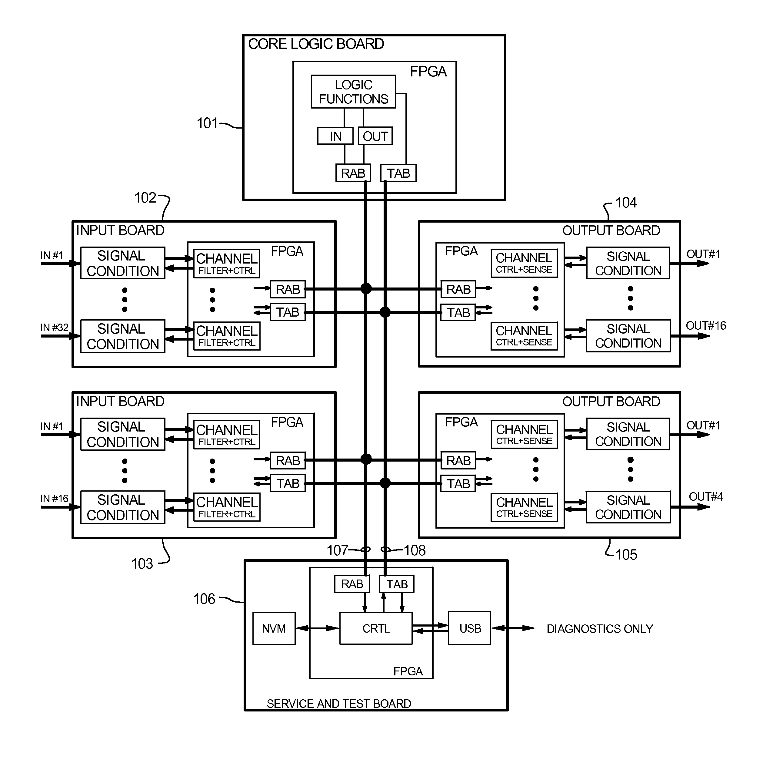
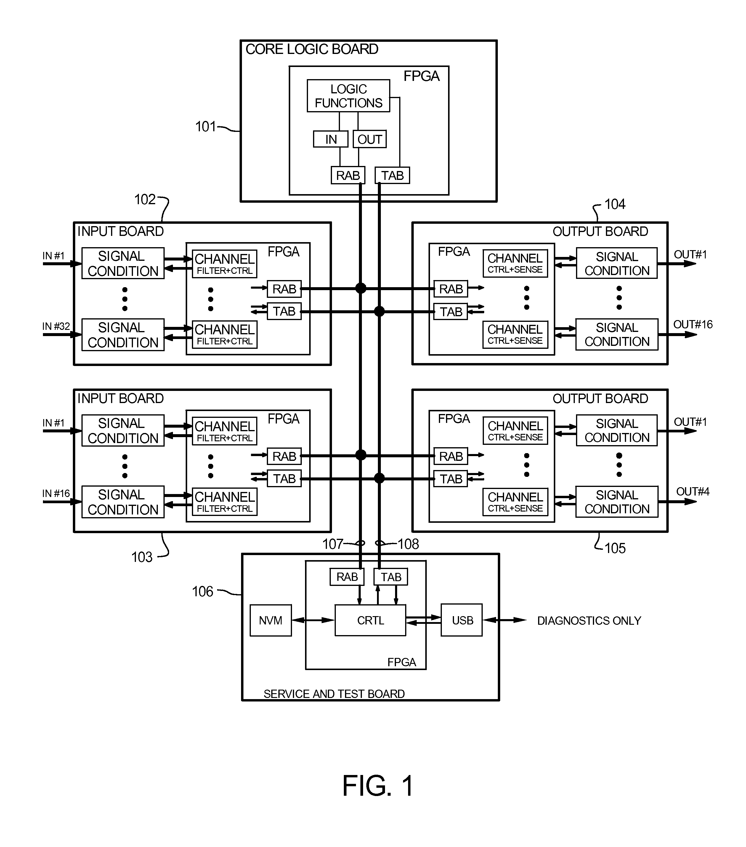
[0016]The advanced logic system (ALS) is a complete control system architecture, based on a hardware platform rather than a software-based microprocessor system. It is significantly different from other software based microprocessor control system architectures, such as a Programmable Logic Controller (PLC) type, by implementing a Field Programmable Gate Array (FPGA) with a simple logic circuit in the central control unit, as opposed to a microprocessor complex with all the required peripherals. The FPGA logic circuits are used to eliminate problems with software based microprocessor systems, such as software common-mode failures. It provides a highly reliable system suitable for safety critical control systems, including reactor protection systems in nuclear plants. The system samples process inputs, provides for digital bus communications, applies a control logic function, and provides for controlled outputs. The architecture incorporates advanced features such as diagnostics, testability, and redundancy on multiple levels. It additionally provides significant improvements in failure detection, isolation, and mitigation to achieve the highest level of integrity and reliability. The ALS offers significant improvements in operability and maintainability compared to other architectures, as well as full flexibility and modularity.

Problems solved by technology

One difficulty in creating a reliable plant protection system is the use of a software based microprocessor.
Software has inherent operational problems that are difficult to resolve.
Even relatively simple systems require a significant amount of program code.
A software-microprocessor system is subject to common mode failure where redundant systems may fail simultaneously due to a fault condition.
In spite of redundancy that may be included within software-microprocessor systems, a fault may occasionally affect enough redundant functions that it is not possible to correctly pick a non-faulty result, and the system will experience a common-mode failure.
The common-mode failure may result from a single fault or several faults.
It is known that microprocessor based systems are vulnerable to common-mode failures where redundant copies of software fail under the same fault.
The common-mode fault, in particular, makes software-microprocessor systems undesirable in a plant protection system.
The system does not include sufficient redundancy in communications or control logic to be suitable for a safety critical system.
The complexity of the system increases the number of components, and therefore, reducing the reliability of the system.
They all have problems associated with software based systems previously described, and they have not been architecturally designed with the kind of redundancy suitable for a safety critical system or a system demanding high reliability.
It is not a parallel operation by utilizing redundant or duplicated control logic and is therefore undesirable for a safety critical system or a system demanding high reliability.

Method used


Image

  • Advanced logic system
  • Advanced logic system
  • Advanced logic system

Examples


Embodiment Construction

[0025]A description of terms related to the present invention follows.

[0026]Advanced Logic System (ALS) is a general title of the hardware architecture platform for the present invention. The ALS is a digital logic controller that is used to monitor and control a process.

[0027]A Field Programmable Gate Array (FPGA) is a semiconductor device containing programmable logic components referred to as “logic blocks,” or “programmable interconnects.” FPGAs are known in the art.

[0028]A circuit board refers to a printed circuit board (PCB), also known as board, a card, or a module.

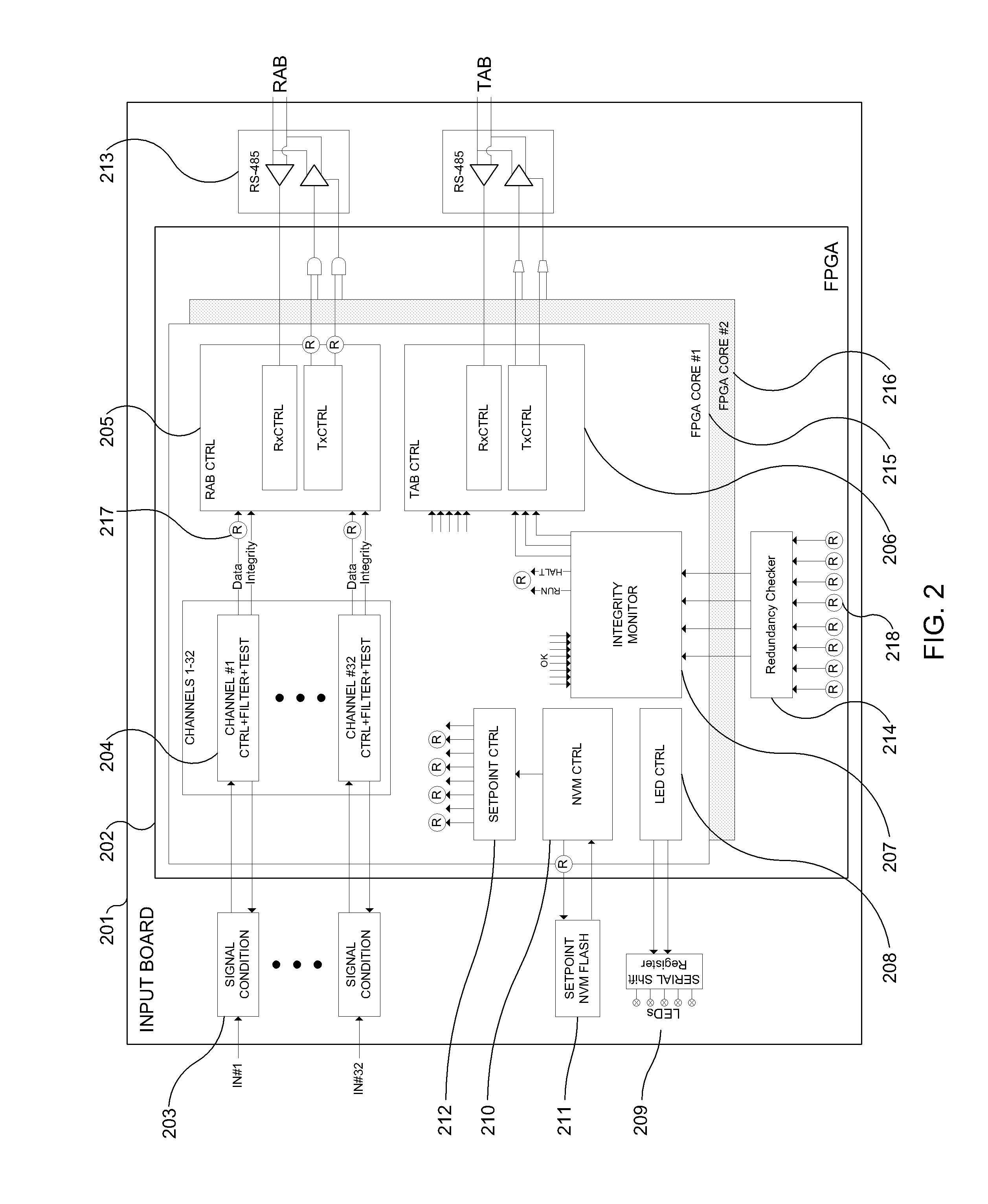
[0029]A channel is the term used for a circuit, which independently can measure or detect a field input, or control a field output. A board typically has a number of channels, such as 4, 8, 16 or 32 channels per board, but other numbers are possible. A channel will typically include signal conditioning, a self test feature, various basic control features, and surge suppression.

[0030]A rack contains a number of boar...


PUM


Abstract

The Advanced Logic System (ALS) is a complete control system architecture, based on a hardware platform rather than a software-based microprocessor system. It is significantly different from other PLC-type control system architectures, by implementing a FPGA in the central control unit. Standard FPGA logic circuits are used rather than a software-based microprocessor which eliminate problems with software based microprocessor systems, such as software common-mode failures. It provides a highly reliable system suitable for safety critical control systems, including nuclear plant protection systems. The system samples process inputs, provides for digital bus communications, applies a control logic function, and provides for controlled outputs. The architecture incorporates advanced features such as diagnostics, testability, and redundancy on multiple levels. It additionally provides significant improvements in failure detection, isolation, and mitigation for the highest level of integrity and reliability.

Description

CROSS REFERENCE TO RELATED APPLICATIONS[0001]Not applicable.STATEMENT REGARDING FEDERALLY SPONSORED RESEARCH OR DEVELOPMENT[0002]Not applicable.REFERENCE TO SEQUENCE LISTING, A TABLE, OR COMPUTER PROGRAM LISTING[0003]Not applicable.BACKGROUND OF THE INVENTION[0004](1) Field of the Invention[0005]The present invention is applicable to industrial process monitoring and control. The present invention is particularly directed toward safety critical control systems, including nuclear plant reactor protection systems, where reliability and integrity are of the highest importance.[0006](2) Description of Related Art[0007]In the field of industrial control systems, including process control systems, redundant monitoring and control paths are used to ensure reliable operation. In the nuclear power industry, it is common to use several levels of redundancy to assure that a particular measurement is known to be valid. In nuclear power plants, independent shut-down and safe-operation systems ar...

Claims


Application Information

Patent Timeline
Patent Type & Authority Patents(United States)
IPC IPC(8): G06F3/00
CPCG06F11/1004G06F11/1608G06F11/1641G06F11/27H04L12/40013H04L12/40176G05B23/0291G06F11/0796G06F11/1616G06F11/2007G06F11/2015G05B2219/24054G05B2219/34334
Inventor SORENSEN, STEEN DITLEVSOGAARD, STEN
Owner WESTINGHOUSE ELECTRIC CORP
Why Eureka
Eureka Blog
Learn More