Apparatus for processing material, and waste container/separating device
a technology for conveying devices and materials, applied in the field of material conveying systems, can solve problems such as occupying space, and achieve the effects of efficient compacting, efficient condensation into the container space, and efficient compacting
- Summary
- Abstract
- Description
- Claims
- Application Information
AI Technical Summary
Benefits of technology
Problems solved by technology
Method used
Image
Examples
second embodiment
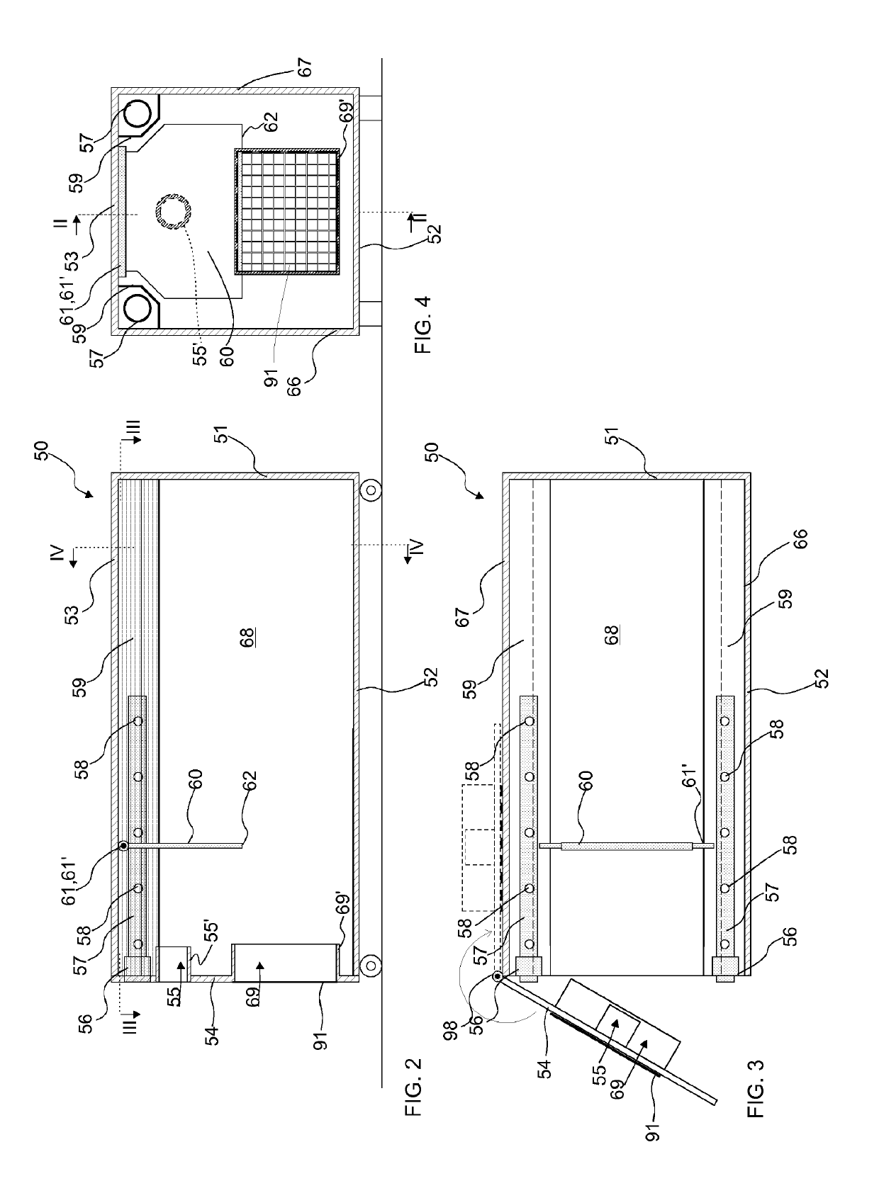
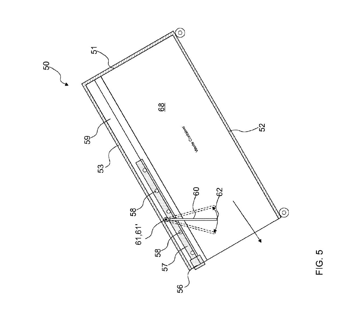
[0043]FIGS. 9 and 10 present the apparatus according to the invention, in which a movable part 89 is arranged in connection with the press device / compactor device 70, which movable part when extended settles in the proximity of the bottom part 62 of the wall 60 arranged in the container space 68 of the waste container / separating device 50 and if necessary supports the wall 60 preventing its essential movement, such as a rotary movement around the axis 61′, towards the wall 54 on the side of the inlet aperture 55. The movable part 89 has a support surface 90, against which the bottom part 62 of the wall 60 can be supported. In the embodiment of FIGS. 9 and 10 the drive apparatus 72 of the press device / compactor device 70 comprises a two-phase arrangement, in which a first drive device 82, 83 is arranged to move the movable part 89 as well as a second drive device 87, 88 and the compression means 71 connected to it into a second position, and from which second position the compression...
third embodiment
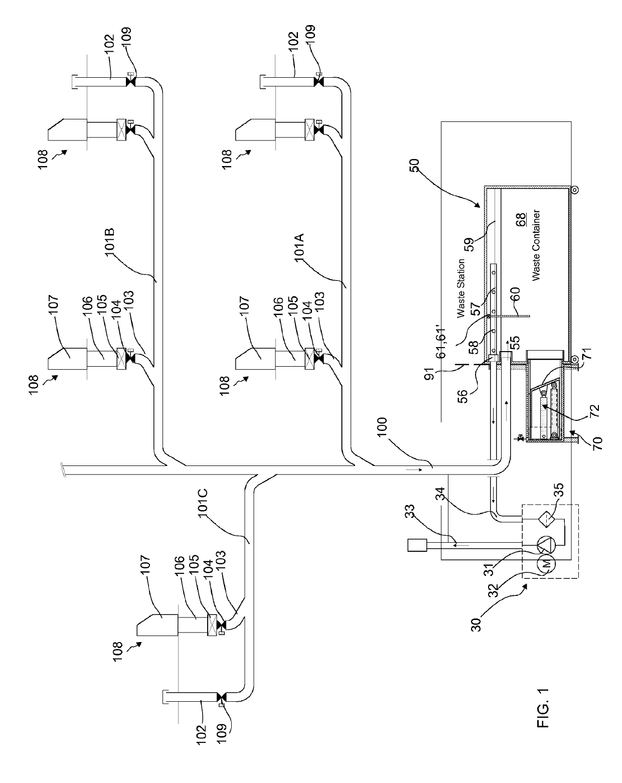
[0045]FIGS. 11-14 further present the invention. Likewise, FIGS. 11-14 present the bringing of a waste container / separating device 50 and connection of it in connection with a press device / compactor device 70 as well as a conveying pipe 100 and a channel 34 of a partial-vacuum generator. In FIG. 11 the waste container / separating device 50 is moved towards the press / compactor. The joint part 80 of the press / compactor device 70 and the end 100 of the conveying pipe as well as the end of the suction channel 34 are arranged in a supported manner in such a way that the necessary joints form, or are formed, when the waste container / separating device 50, the counterparts on it, the press aperture 69, inlet aperture 55 and connection 56 are brought against the joint part 80 and the end 100 of the conveying pipe and the end of the suction channel 34. According to one embodiment the hatch 91 is arranged to cover the aperture 69, which hatch is displaced from the position of FIG. 11 upwards in...
fourth embodiment
[0051]FIGS. 15-22 present the apparatus according to the invention, in which a movable part 89 is arranged in connection with the press device / compactor device 70, which movable part when extended settles in the proximity of the bottom part 62 of the wall 60 arranged in the container space 68 of the waste container / separating device 50 and if necessary supports the wall 60 preventing its essential movement, such as a rotary movement around the axis 61′, towards the wall 54 on the side of the inlet aperture 55. The movable part 89 has a support surface 90, against which the bottom part 62 of the wall 60 can be supported. In the embodiment of the figures the drive apparatus 72 of the press device / compactor device 70 comprises a two-phase arrangement, in which a first drive device 82, 83 is arranged to move a movable part 89 as well as a second drive device 87, 88 and the compression means 71 connected to it into a second position, and from which second position the compression means i...
PUM
 Abstract
Description
Claims
Application Information
 - R&D
- Intellectual Property
- Life Sciences
- Materials
- Tech Scout
- Unparalleled Data Quality
- Higher Quality Content
- 60% Fewer Hallucinations
Browse by: Latest US Patents, China's latest patents, Technical Efficacy Thesaurus, Application Domain, Technology Topic, Popular Technical Reports.
© 2025 PatSnap. All rights reserved.Legal|Privacy policy|Modern Slavery Act Transparency Statement|Sitemap|About US| Contact US: help@patsnap.com


