
Hydraulic control device and hydraulic control method for vehicle

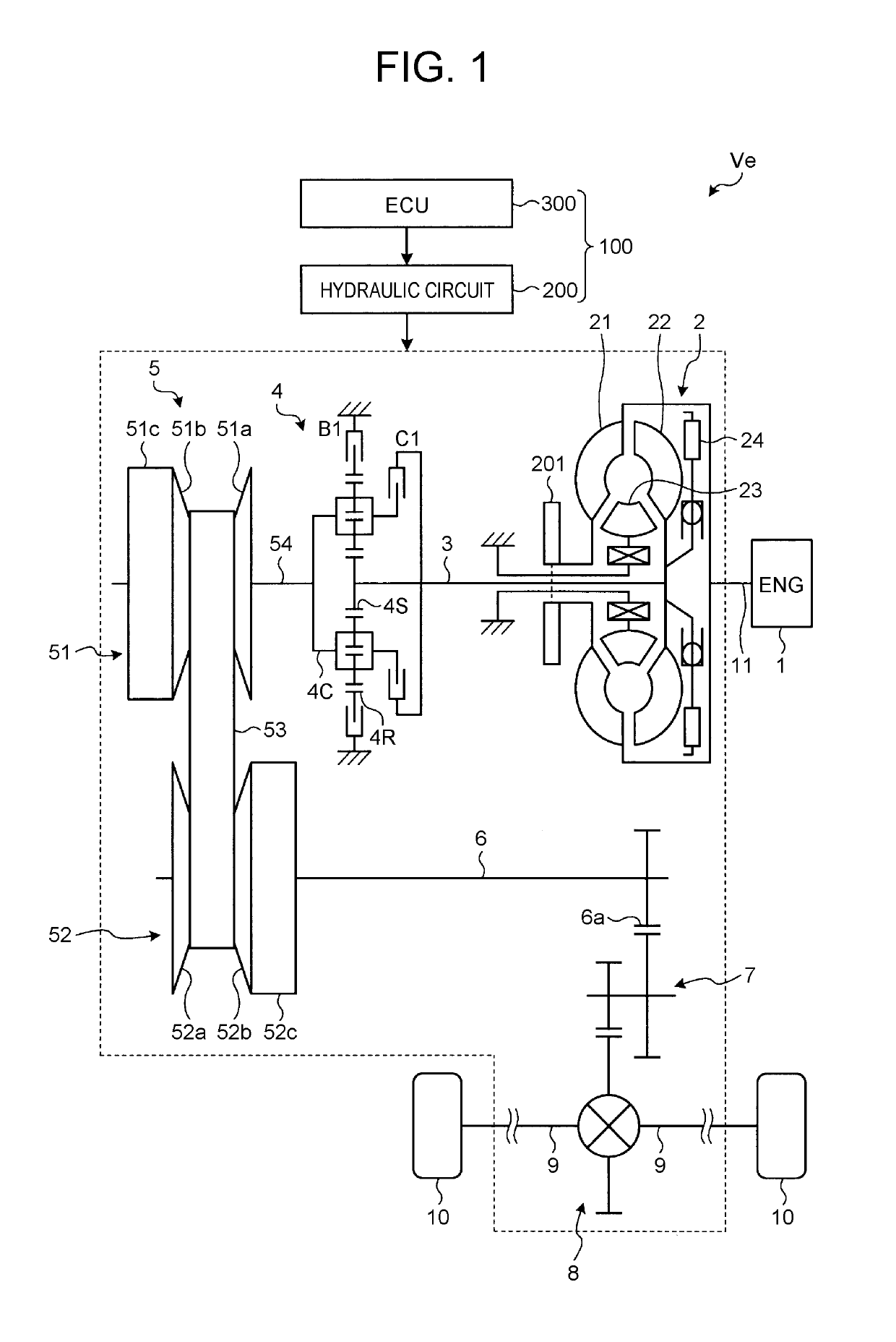
a technology of hydraulic control device and hydraulic control method, which is applied in the direction of fluid gearing, gearing, servomotor, etc., can solve the problems of inability to control the actual discharge hydraulic pressure of the mechanical oil pump mounted in the vehicle, the inability to accurately measure and the time lag until the actual discharge hydraulic pressure deficiency is resolved, so as to suppress the deterioration of fuel efficiency, reduce the load of the electric oil pump, and reduce the power consumption of the electric oil

Active Publication Date: 2019-10-08
TOYOTA JIDOSHA KK
View PDF18 Cites 0 Cited by
  • Summary
  • Abstract
  • Description
  • Claims
  • Application Information

AI Technical Summary

Benefits of technology

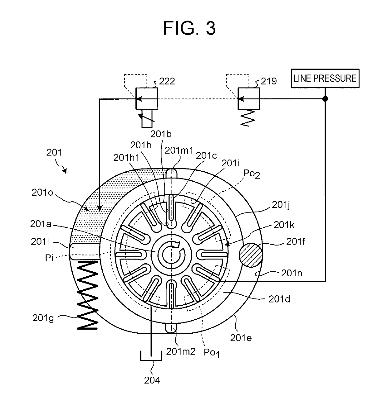
[0008]Such a configuration makes it possible to calculate the target discharge volume of the mechanical variable-capacity oil pump in consideration of the amount of oil leakage from the mechanical variable-capacity oil pump. Accordingly, even when the amount of oil leakage from the mechanical variable-capacity oil pump increases as the engine rotation speed becomes higher, the mechanical variable-capacity oil pump can be controlled with sufficient responsiveness as compared with the case of performing feedback-control of the mechanical variable-capacity oil pump.
[0009]The hydraulic control device further may include an electric oil pump configured to supply hydraulic pressure to the drive unit. The electronic control unit may be configured to: (i) calculate amount of fuel consumption of the engine corresponding to an increment of a driving electric power amount of the electric oil pump when the electric oil pump is driven at an operating point more efficient than a current operating point; (ii) compare the amount of fuel consumption of the engine corresponding to the increment of the driving electric power amount of the electric oil pump, with a decrease amount of fuel consumption of the engine caused by decrease in the discharge flow volume of the mechanical variable-capacity oil pump; and (iii) when the decrease amount is larger than the fuel consumption corresponding to the increment of a driving electric power amount of the electric oil pump, drive the electric oil pump at the operating point more efficient than the current operating point, with driving the mechanical variable-capacity oil pump such that the discharge flow volume of the mechanical variable-capacity oil pump is decreased.
[0010]According to such a configuration, the electric oil pump is driven at the driving point more efficient than the current operating point, and the discharge flow volume of the mechanical variable-capacity oil pump is decreased. Therefore, fuel efficiency can be enhanced.
[0012]According to such a configuration, the target discharge volume of the mechanical variable-capacity oil pump is set to a maximum discharge volume, when fuel supply to the engine is stopped. Accordingly, the load of the electric oil pump can be decreased, and the power consumption of the electric oil pump can be reduced, which makes it possible to suppress deterioration of the fuel efficiency.
[0013]According to the vehicular hydraulic control device according to the present disclosure, a target discharge volume of the mechanical variable-capacity oil pump is calculated using the parameter about the drive unit of the vehicle, and the mechanical variable-capacity oil pump is controlled based on the calculated target discharge volume. This makes it possible to control the mechanical variable-capacity oil pump with sufficient responsiveness, without using the measuring device of an actual discharge hydraulic pressure.

Problems solved by technology

In contrast, the discharge hydraulic pressure of a mechanical oil pump (MOP) mounted in vehicles cannot be controlled as it depends on engine rotation speed.
Accordingly, cost and disposition space for the measuring device of the actual discharge hydraulic pressure becomes necessary.
However, when the target discharge oil amount is increased after an actual discharge hydraulic pressure deficiency is detected, there is a time lag until the actual discharge hydraulic pressure deficiency is resolved.
This causes a problem in terms of responsiveness of the control of the mechanical variable-capacity oil pump.

Method used


Image

  • Hydraulic control device and hydraulic control method for vehicle
  • Hydraulic control device and hydraulic control method for vehicle
  • Hydraulic control device and hydraulic control method for vehicle

Examples


second embodiment

[0111]The flow of the discharge flow volume and discharge hydraulic pressure calculation processing that is the second embodiment of the present disclosure will be described with reference to FIG. 9.

[0112]FIG. 9 is a flowchart illustrating the flow of the discharge flow volume and discharge hydraulic pressure calculation processing that is the second embodiment of the present disclosure. The flowchart illustrated in FIG. 9 is started at the timing when the processing of step S1 illustrated in FIG. 4 is completed. Then, the discharge flow volume and discharge hydraulic pressure calculation processing proceeds to step S51.

[0113]In the processing of step S51, the ECU 300 determines whether or not the sum of the sheave-clutch control system flow volume Qpl and the T / C control system flow volume Qsec is equal to or less than the discharge flow volume Qmop_main_max of the main port Po1 at the time of the maximum discharge volume of the variable-capacity MOP 201. As a result of determinati...


PUM


Abstract

The hydraulic control device includes: a mechanical variable-capacity oil pump; and an electronic control unit configured to calculate a target discharge volume of the mechanical variable-capacity oil pump using a plurality of parameters of the transmission, and control the mechanical variable-capacity oil pump based on the target discharge volume.

Description

INCORPORATION BY REFERENCE[0001]The disclosure of Japanese Patent Application No. 2016-229011 filed on Nov. 25, 2016 including the specification, drawings and abstract is incorporated herein by reference in its entirety.BACKGROUND1. Technical Field[0002]The present disclosure relates to a hydraulic control device and hydraulic control method for vehicle that supplies hydraulic pressure to a drive unit of the vehicle using a mechanical variable-capacity oil pump driven by an engine of the vehicle.2. Description of Related Art[0003]Generally, a discharge hydraulic pressure of an electric oil pump (EOP) mounted in vehicles can be controlled by controlling rotation speed of a motor that is an actuator of the EOP. In contrast, the discharge hydraulic pressure of a mechanical oil pump (MOP) mounted in vehicles cannot be controlled as it depends on engine rotation speed. However, the discharge hydraulic pressure of a mechanical variable-capacity oil pump (variable-capacity MOP) can be cont...

Claims


Application Information

Patent Timeline
Patent Type & Authority Patents(United States)
IPC IPC(8): F16H61/00F16H59/68F16H61/14F16H61/662F16H57/04F16H61/02F16H59/70F16H59/14F16H59/74F16H59/42
CPCF16H57/0436F16H61/66259F16H61/0025F16H61/66227F16H61/143F16H59/68F16H59/74F16H2059/147F16H61/0031F16H59/70F16H2059/743F16H61/0206F16H59/42F16H59/14F16H2061/0037F16H57/046F15B11/08F15B21/08F16H61/4035F16H61/0262
Inventor NAGASATO, YUASAOKA, HIRONORIITO, YOSHIO
Owner TOYOTA JIDOSHA KK
Learn More