
Method and a system for supporting a frame of a mineral material crusher and a crushing plant

a technology for mineral material crushers and crushing plants, applied in grain treatment and other directions, can solve the problems of large force in the machine direction, large stress on fixing devices, and load in the crushers

Active Publication Date: 2019-10-08
METSO OUTOTEC (FINLAND) OY
View PDF14 Cites 0 Cited by
  • Summary
  • Abstract
  • Description
  • Claims
  • Application Information

AI Technical Summary

Benefits of technology

The invention improves the efficiency and reduces energy consumption of mineral material processing plants and crushers. It also increases the durability of mechanical components, keeps the crusher straight, and reduces wear and tear. Additionally, it improves environmental friendliness and reduces manufacturing costs. The mobile plant is designed to be lighter, flexible, and more reliable.

Problems solved by technology

The crushing forces and the material dropping into the throat of the crusher cause loads in the crusher, the loads spreading through the crusher frame to the surrounding structures.
The dropping of a large stone arriving into the throat and the crushing of the stone causes large forces in the machine direction.
In case of a movable processing plant, particularly equipped with a track base, the fixing devices are subjected to even larger stresses.
For example when a crushing plant moves on an uneven terrain the known fixing method causes forces which stress the frame structures of the crusher.
In that situation the fixing devices in said corners are subjected to large vertical stresses which also can lead to breaking of for example bolts, rubber dampers, or welding seams of the supports.
A vertical flexibility of the existing fixing method is small.
The twisting of the crusher frame causes misalignment between the pitman and the frame which shortens life of the toggle plate and bearings of the jaw crusher.
The accuracy required of the body of the processing plant increases manufacturing costs.

Method used


Image

  • Method and a system for supporting a frame of a mineral material crusher and a crushing plant
  • Method and a system for supporting a frame of a mineral material crusher and a crushing plant
  • Method and a system for supporting a frame of a mineral material crusher and a crushing plant

Examples


Embodiment Construction

[0054]In the following description, like numbers denote like elements. It should be appreciated that the illustrated drawings are not entirely in scale, and that the drawings mainly serve the purpose of illustrating some example embodiments of the invention.

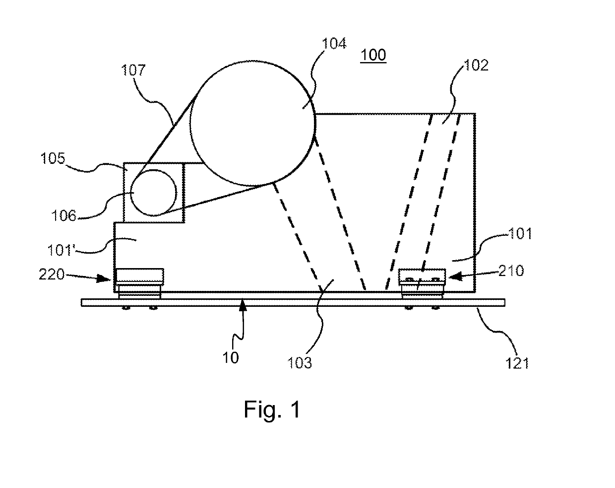
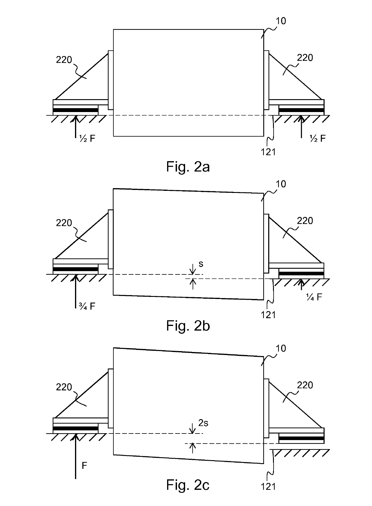
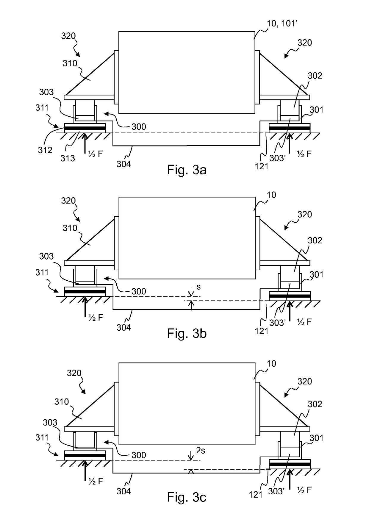
[0055]FIGS. 1 to 2c are described in connection with the prior art. The inventor has found that the undesired twisting of the crusher frame can be reduced with a simple and cost effective solution. The crusher according to FIG. 1 can also be used as operation object of embodiments of the present invention so that instead of the support devices of FIGS. 1 and 2 a support device according to an embodiment of the invention is used, for example the second support device shown in FIGS. 3a-3c, 4 or 5. With help of different embodiments of the invention all support devices can bear load without crusher frame twisting.

[0056]Support devices according to different embodiments of the invention are shown in FIGS. 3a-3c, 4 and 5. FIGS. 3a-3c ...


PUM


Abstract

A method and a system for supporting a frame of a mineral material crusher on a body of a crushing plant and a mineral material processing plant. The crusher frame is supported by first support devices in place in relation to the body of the crushing plant at first support points and by at least two second support devices at second support points. The second support device has an adjusting member between the crusher frame and the body of the crushing plant, and at least one second support device is configured to move the frame of the crusher vertically in relation to the body of the crushing plant. The adjusting member has a cylinder and a piston inside the cylinder which define an adjusting volume therebetween. A pressure is formed from a load above the adjusting member and is arranged to form into the adjusting volumes of the adjusting members.

Description

CROSS-REFERENCE TO RELATED APPLICATIONS[0001]This application claims priority to PCT / FI2014 / 050407, filed May 26, 2014, and published in English on Dec. 18, 2014 as publication number WO 2014 / 199004, which claims priority to FI Application No. 20135652, filed Jun. 14, 2013, incorporated herein by reference.TECHNICAL FIELD[0002]The invention relates generally to supporting a frame of a mineral material crusher on a base. The invention relates particularly, though not exclusively, to preventing twisting of a frame of a jaw crusher.BACKGROUND ART[0003]Mineral material, for example rock, is gained from the earth for processing by exploding or excavating. The rock can also be natural rock and gravel or construction waste. Mobile crushers and stationary crushing applications are used in crushing. An excavator or wheeled loader loads the material to be crushed into the crusher's feed hopper from where the material to be crushed may fall in a crushing chamber of a crusher or a feeder moves ...

Claims


Application Information

Patent Timeline
Patent Type & Authority Patents(United States)
IPC IPC(8): B02C21/02B02C1/04B02C1/06B02C1/00B02C1/02B02C23/00
CPCB02C1/005B02C1/06B02C21/026B02C1/00B02C1/02B02C1/043B02C23/00B02C25/00
Inventor JONKKA, JARI
Owner METSO OUTOTEC (FINLAND) OY
Learn More