Tangentially mounted indexable cutting insert with convex-shaped minor side surfaces and concave-shaped end surfaces

a technology of indexable cutting inserts and minor side surfaces, which is applied in the field of cutting inserts, can solve the problems of inaccurate positioning of the contact between the insert pad and the cutter pocket, reduced surface, and inability to accurately locate the contact, etc., and achieve the effect of accurately tangential mounting and extending the length of the cutting inser

Active Publication Date: 2019-09-24
KENNAMETAL INC
View PDF31 Cites 0 Cited by
  • Summary
  • Abstract
  • Description
  • Claims
  • Application Information

AI Technical Summary

Benefits of technology

[0003]The problem of accurately tangentially mounting a cutting insert in the pocket is solved by providing minor side surfaces with a convex shape, and end surfaces with a concave-shaped seating surface that extends the length of the cutting insert.
[0004]The convex-shaped minor side surfaces allow for slight misalignment of the pocket with respect to the work piece without negatively effecting surface finish. This allows an increase in finish quality without the associated expense of a precision ground insert or unusually tight manufacturing tolerances
[0005]The concave-shaped seating surfaces that extend the length of the cutting insert enable the cutting insert to have better control at the point of contact, thereby improving stability of the cutting insert when mounted in the cutter pocket.

Problems solved by technology

One problem encountered with tangentially mounting a cutting insert in the pocket is that it requires that the tangential seating surface be reduced to allow room for cutting edges and associated cutting geometry.
The reduction in size of the tangential seating pad and the tendency for carbide to distort during manufacturing, makes it difficult to accurately locate the contact of the insert pad to the cutter pocket.
In addition, multiple, planar seating arrangements lend themselves to smaller contact areas and inaccurate location of the contact.

Method used


Image

  • Tangentially mounted indexable cutting insert with convex-shaped minor side surfaces and concave-shaped end surfaces
  • Tangentially mounted indexable cutting insert with convex-shaped minor side surfaces and concave-shaped end surfaces
  • Tangentially mounted indexable cutting insert with convex-shaped minor side surfaces and concave-shaped end surfaces

Examples


Embodiment Construction

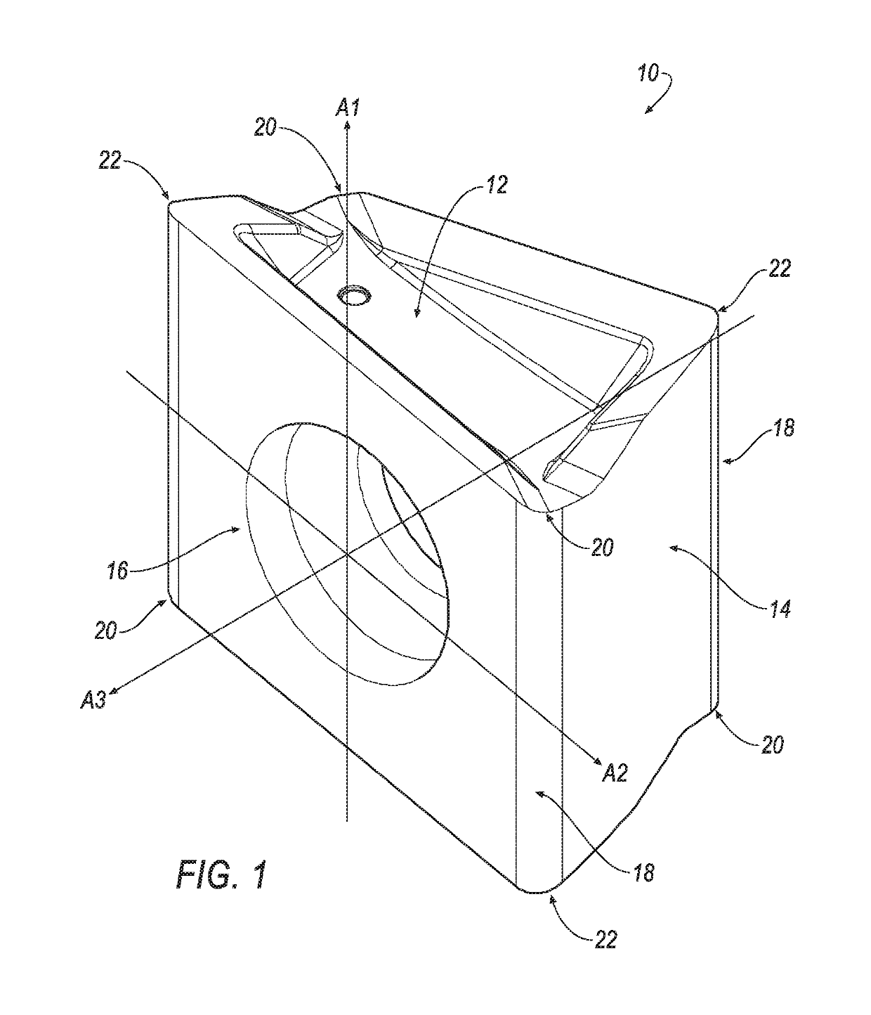
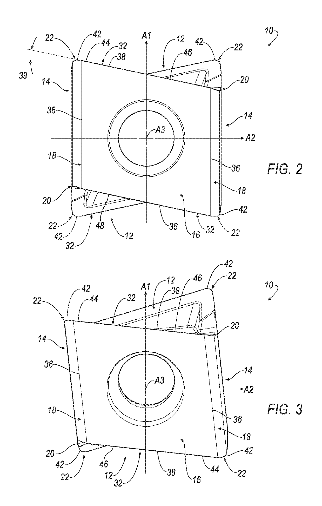
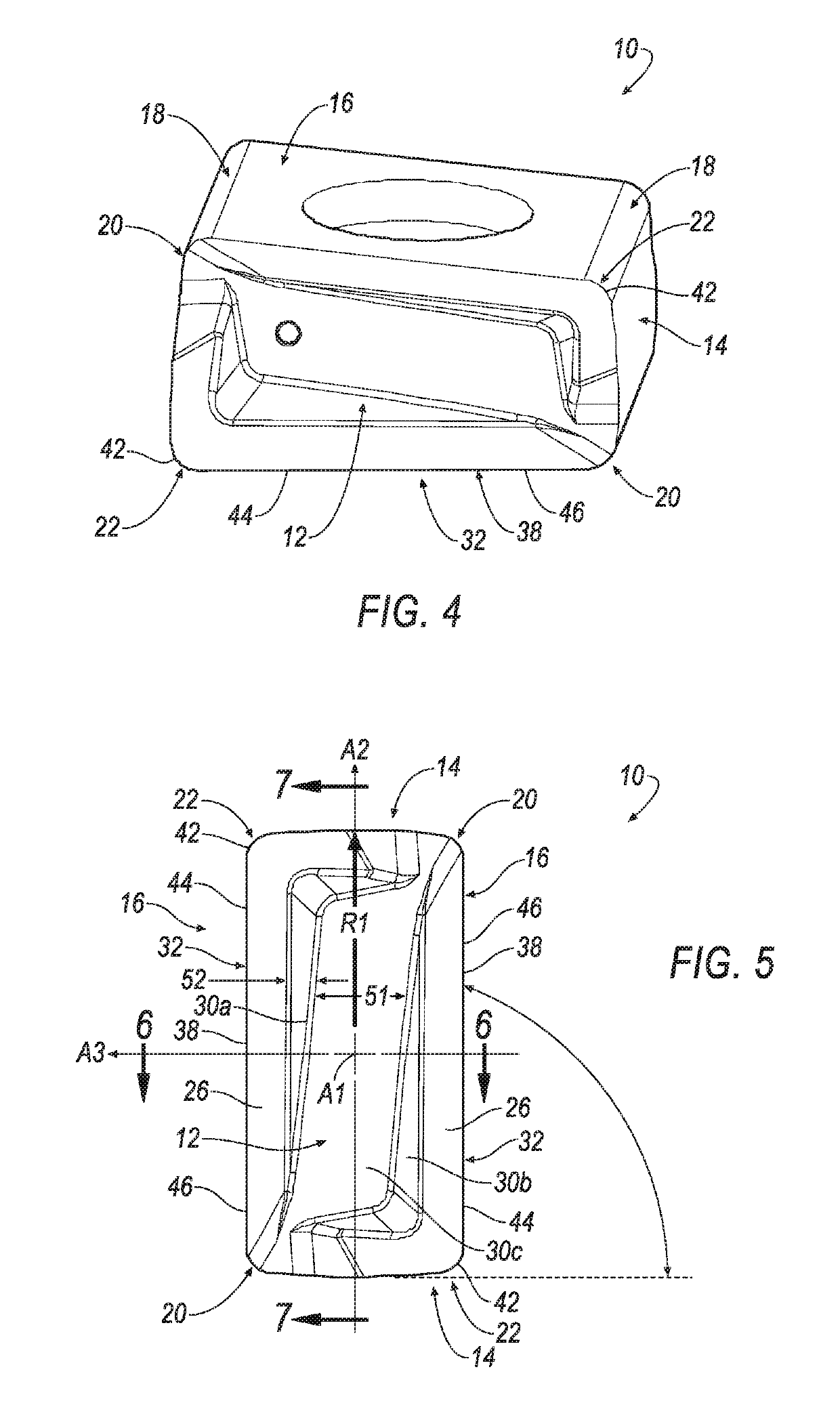
[0018]Referring now to FIGS. 1-7, a cutting insert 10 is shown according to an embodiment of the invention. In general, the cutting insert 10 is indexable and tangentially mounted in a pocket of a milling cutter (not shown). The cutting insert 10 is typically manufactured by form-pressing and sintering carbide powders using methods well-known in the art. The cutting insert 10 is generally rectangular in shape and has two identical opposing end seating surfaces 12, two identical opposing minor side surfaces 14 extending between the two opposing end seating surfaces 12, two identical opposing major side surfaces 16 extending between the end surfaces 12 and the minor side surfaces 14. Each end surface 12 has 180° rotational symmetry about a first central axis A1 passing through the two end surfaces 12, each minor side surface 14 has 180° rotational symmetry about a second central axis A2 passing through the two minor side surfaces 14, and each major side surface 16 has 180° rotational ...


PUM


Abstract

A cutting insert having two opposing end surfaces, two identical opposing major side surfaces and two identical opposing minor side surfaces. Each end surface of the insert has a concave-shaped seating surface for contacting the insert pocket the insert pocket along an entire length of the cutting insert. The minor side surfaces are convex-shaped. The concave-shaped seating surface and the convex-shaped minor side surfaces enable the cutting insert to be accurately tangentially mounted in the insert pocket.

Description

FIELD OF THE INVENTION[0001]In general, the invention relates to a cutting insert, and in particular to a cutting insert for a milling cutter that is tangentially mounted in the cutter pocket with convex-shaped minor side surfaces and concave-shaped end surfaces.BACKGROUND OF THE INVENTION[0002]One problem encountered with tangentially mounting a cutting insert in the pocket is that it requires that the tangential seating surface be reduced to allow room for cutting edges and associated cutting geometry. The reduction in size of the tangential seating pad and the tendency for carbide to distort during manufacturing, makes it difficult to accurately locate the contact of the insert pad to the cutter pocket. In addition, multiple, planar seating arrangements lend themselves to smaller contact areas and inaccurate location of the contact. Thus, it would be desirable to provide a cutting insert that can be accurately tangentially mounted in the pocket of a cutting tool.SUMMARY OF THE IN...

Claims


Application Information

Patent Timeline
Patent Type & Authority Patents(United States)
IPC IPC(8): B23C5/20B23C5/06
CPCB23C5/207B23C5/06B23C2200/164B23C2200/165B23C2200/0494B23C2200/367B23B27/00B23C5/202
Inventor BRUNETTO, LANCE DAVID
Owner KENNAMETAL INC
Why Eureka
Try Eureka