Fine comminutor

a comminutor and fine technology, applied in the field of comminution devices, can solve the problems of inability to comminution into very short fibre parts, and achieve the effects of increasing complexity, cost-effective production, and keeping structural simplicity

Active Publication Date: 2019-07-11
HUGO VOGELSANG MASCHINENBAU GMBH
View PDF0 Cites 0 Cited by
  • Summary
  • Abstract
  • Description
  • Claims
  • Application Information

AI Technical Summary

Benefits of technology

[0031]It is further preferred that the second cutting element is mounted on a hub, wherein the hub comprises at least one radial recess having a mounting surface disposed at an angle to the axis of rotation, wherein the second cutting element is mounted on the mounting surface. The second cutting elements can be kept structurally simple in this way. It is advantageous when the second cutting elements are as simple as possible, since they wear out and have to be replaced. Cost-effective production is therefore particularly preferred. The increased complexity that occurs due to the inclination is transmitted to the hub according to this emb

Problems solved by technology

Although the known comminutors can cut the fibres, a commin

Method used


Image

  • Fine comminutor
  • Fine comminutor
  • Fine comminutor

Examples


Embodiment Construction

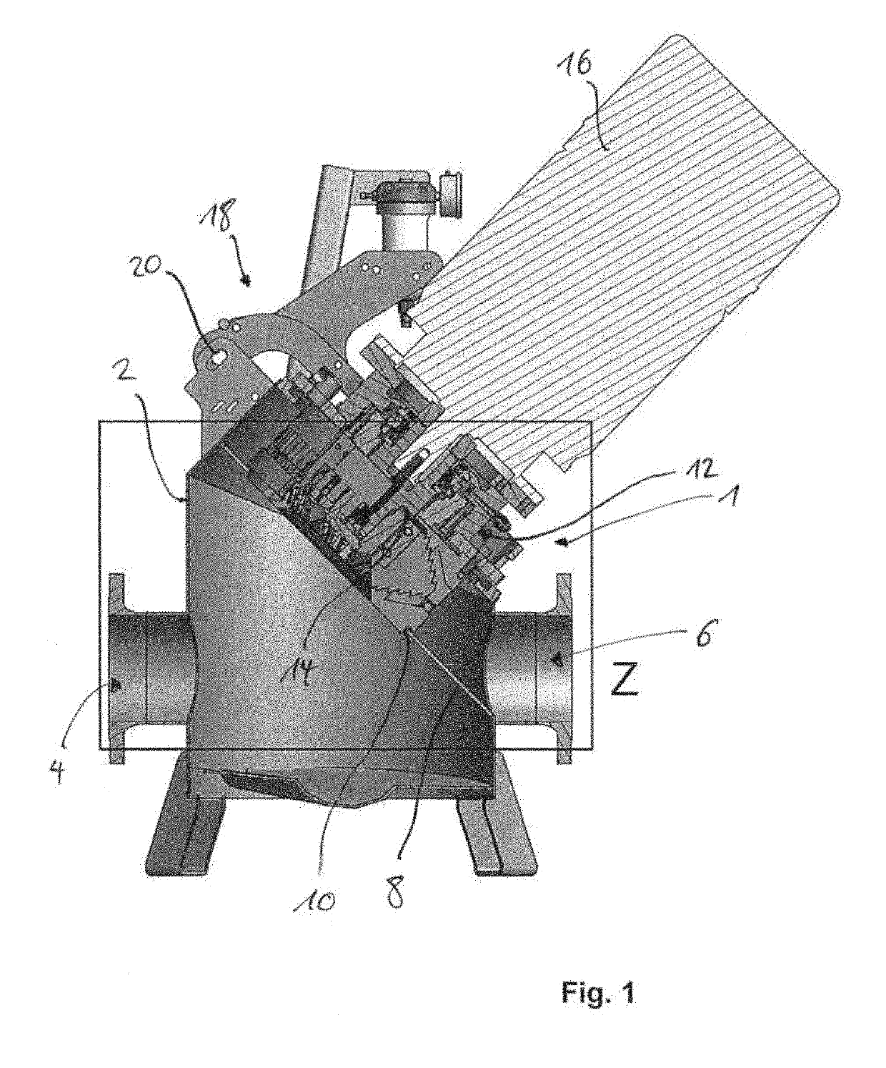
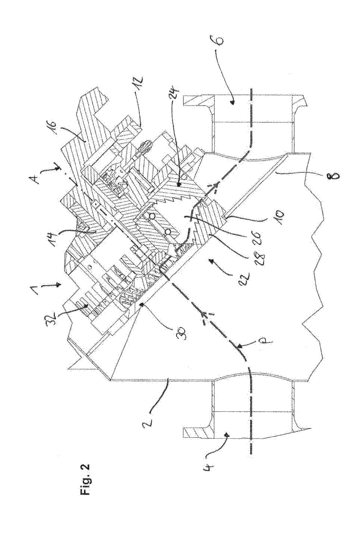
[0043]A comminution device 1 is disposed in a pot 2 of a pipe system. The pot 2 comprises an inlet 4 and an outlet 6, which can be flanged to corresponding tubes. Inside, the pot 2 comprises a separating plate 8 that separates inlet 4 and outlet 6 from each other. A passage 10 is implemented in the separating plate 8, in which passage the comminution device 1 is inserted. The comminution device 1 is described in more detail with reference to the further figures. It comprises a main housing 12, in which a drive shaft 14 is supported, which is coupled to a drive 16. The entire comminution device 1 is pivotally mounted on the pot 2 via a pivoting mechanism 18 and can be pivoted away from the pot 2 about a pivot point 20 with reference to FIG. 1. This is used to perform maintenance on the comminution device 1 and the pot 2, for example, in the event that individual parts are jammed there.

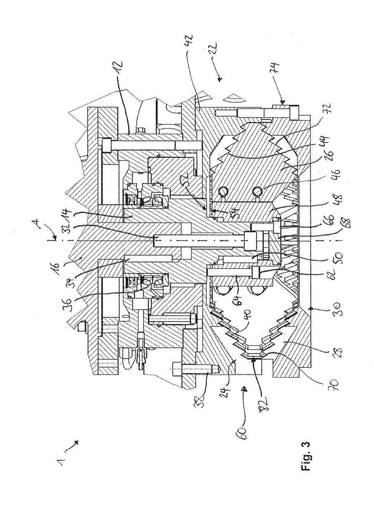
[0044]The comminution device 1 (see FIG. 2) comprises a cutting unit 22, in which a plurality of fir...


PUM


Abstract

A comminution device comprises a plurality of first cutting elements having first serrated cutting edges disposed on a first circular path; a second cutting element having a second serrated cutting edge corresponding to the first serrated cutting edges for cutting through cutting material, the second cutting element being displaceable about an axis of rotation on a second circular path concentric with the first circular path. The second serrated cutting edge comprises a plurality of jags and each jag comprises a radially inner flank and a radially outer flank, each at an angle to the axis of rotation. A drive rotationally drives the second cutting element about the axis of rotation and an adjustment mechanism by which the plurality of first cutting elements and the second cutting element are displaceable relative to each other axially in the direction of the axis of rotation, that a cutting gap between them is adjustable.

Description

CROSS-REFERENCE TO FOREIGN PRIORITY APPLICATION[0001]The present application claims the benefit under 35 U.S.C. §§ 119(b), 119(e), 120, and / or 365(c) of PCT / EP2017 / 073793 filed Sep. 20, 2017, which claims priority to German Application No. 202016105242.4 filed Sep. 20, 2016.FIELD OF THE INVENTION[0002]The invention relates to a comminution device having first and second cutting elements which are rotatable relative to each other.BACKGROUND OF THE INVENTION[0003]A generic comminution device is known, for example, from EP 2 613 884 B1. Such cutting devices are used to comminute solids, solid masses, or liquids containing solids and are used in particular as a so-called wet comminutor, for example, in the food industry, in the preparation of bio-suspensions for further energetic use, or to prepare flowable mixtures mixed with solids in other agricultural uses and, in this case, to comminute the solids contained therein.[0004]A further such cutting device is known from PCT / EP 2010 / 05380...

Claims


Application Information

Patent Timeline
IPC IPC(8): B02C18/00B02C18/18
CPCB02C18/0092B02C18/18B02C2018/188B02C18/06B02C18/16B02C2201/06
Inventor BURHORST, TORSTEN
Owner HUGO VOGELSANG MASCHINENBAU GMBH
Why Eureka
Try Eureka