Continuous casting method of steel

a casting method and steel technology, applied in the direction of metal rolling arrangement, etc., can solve the problems of similar drawbacks, and achieve the effect of reducing the center segregation of the cast slab and reducing the time and effor

Active Publication Date: 2019-09-10
JFE STEEL CORP
View PDF11 Cites 0 Cited by
  • Summary
  • Abstract
  • Description
  • Claims
  • Application Information

AI Technical Summary

Benefits of technology

[0014]According to the present disclosure, even when a drawing speed of a cast slab is changed, it is possible to prevent a solidification completion position from being largely changed from a predetermined target position without requiring large time and effort. Accordingly, by effectively carrying out a solidification last-stage soft rolling reduction method, the formation of pores and the flow of a concentrated molten steel in the center portion of the cast slab can be suppressed and hence, the center segregation of the cast slab can be effectively suppressed.

Problems solved by technology

Further, the similar drawbacks occur also with respect to an offshore structure, a storage tank, an oil tank and the like.

Method used


Image

  • Continuous casting method of steel
  • Continuous casting method of steel
  • Continuous casting method of steel

Examples


example

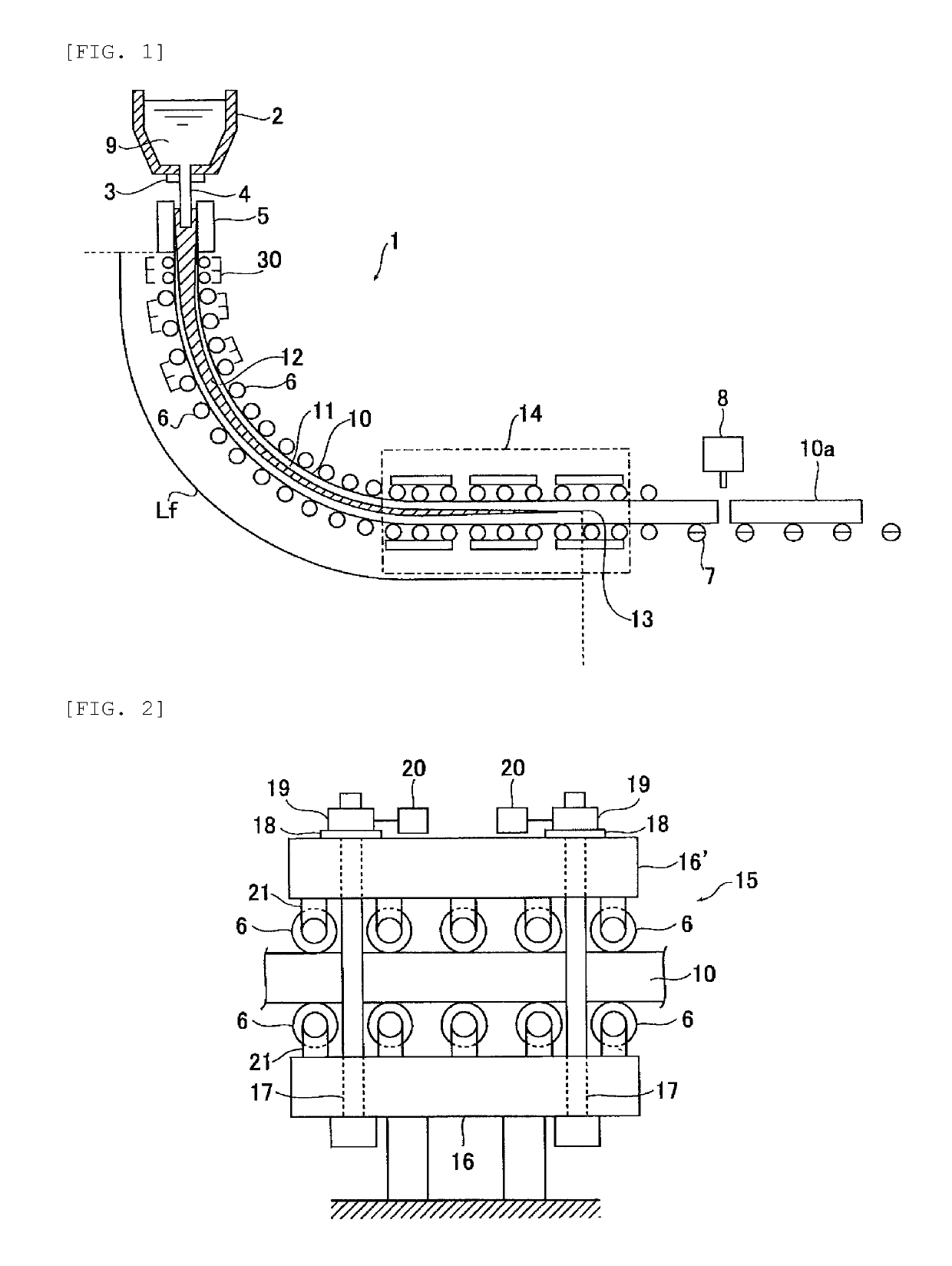
[0056]The continuous casting where a cast slab made of low carbon aluminum killed steel is manufactured using the slab continuous casting machine 1 shown in FIG. 1 was performed plural times. In all continuous casting operations, a size of a mold 5 was set such that the cast slab 10 has a width of 2100 mm and a thickness of 250 mm. The soft rolling reduction zone 14 was arranged such that the cast slab 10 was reduced by rolling from a point of time that a temperature became the one corresponding to a solid phase fraction of 0.02 at a thickness center portion of the cast slab to a point of time that a temperature became the one corresponding to the solid phase fraction of 0.8 at the thickness center portion of the cast slab. The length Lf of the cast slab 10 along the casting direction from the exit of the mold 5 to the solidification completion position 13 was set to 28 meter (=target length Lt).

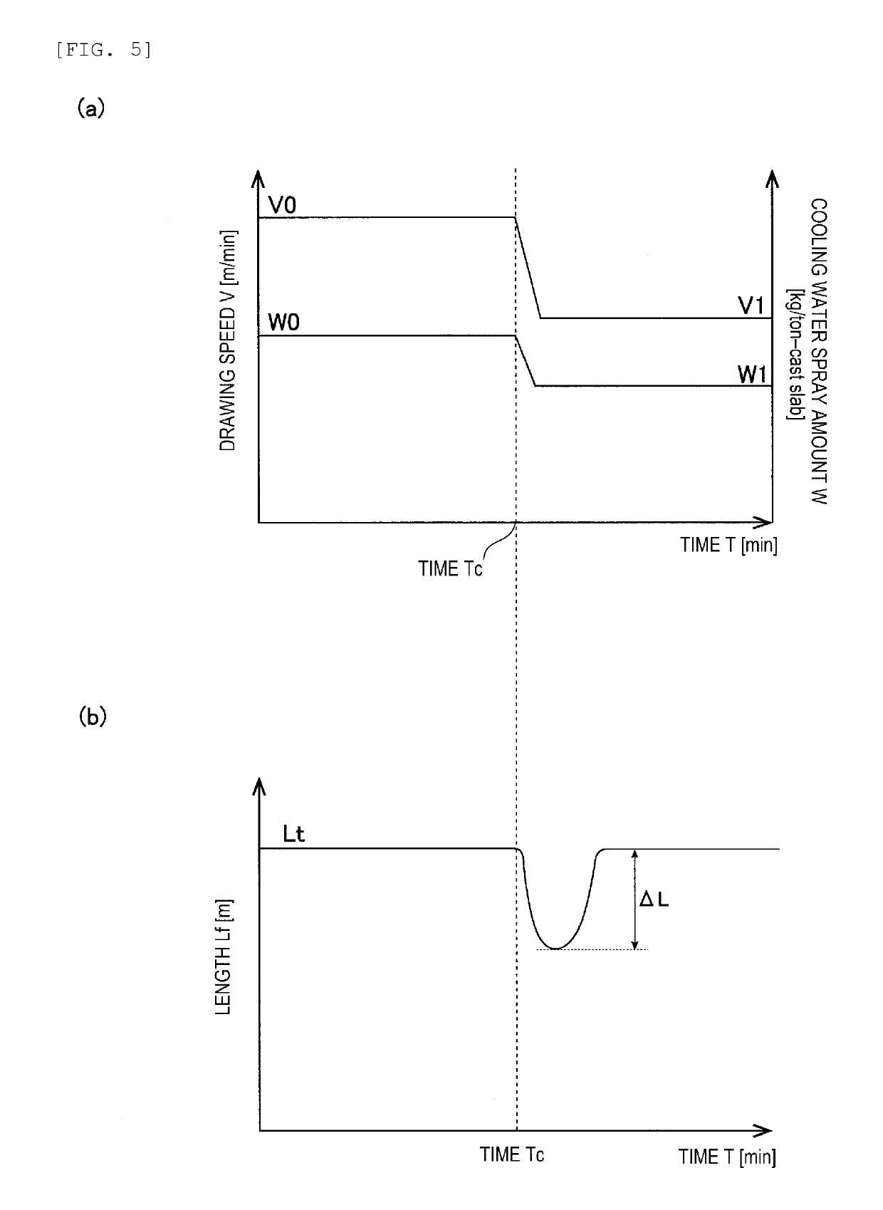
[0057]In all continuous casting operations, a drawing speed V of the cast slab was chang...


PUM

PropertyMeasurementUnit
thicknessaaaaaaaaaa
widthaaaaaaaaaa
length Lfaaaaaaaaaa

Abstract

Provided is a continuous casting method of steel that prevents a solidification completion position from being changed even when a drawing speed V of a cast slab is changed. The method includes drawing a cast slab by setting a drawing speed V0 while spraying cooling water to the cast slab at a cooling water spray amount W0 [kg / ton-cast slab]. Then, changing the drawing speed to the speed V1 while spraying cooling water to the cast slab at a cooling water spray amount W1 [kg / ton-cast slab]. The method further includes spraying cooling water to the cast slab at a cooling water spray amount Wt [kg / ton-cast slab] during a period of time t that is obtained by dividing a target length Lt by the drawing speed V0. The water spray amount Wt satisfying either formula (1): Wt<W1 under a condition of V1<V0, or formula (2): Wt>W1 under a condition of V1>V0.

Description

TECHNICAL FIELD[0001]The present disclosure relates to a continuous casting method of steel where a solidification completion position at which solidification of molten steel in a cast slab casted by a continuous casting machine is completed is fixed to a predetermined target position.BACKGROUND ART[0002]In continuous casting of steel, in a final stage of solidification, a suction flow of non-solidified molten steel (also referred to as “non-solidification layer” when necessary) is generated in the drawing direction of a cast slab along with solidification shrinkage. In the non-solidification layer, solute elements such as carbon (C), phosphorus (P), sulfur (S), manganese (Mn) and the like are concentrated, and the so-called center segregation is generated when concentrated molten steel flows into a center portion of a cast slab and is solidified.[0003]The center segregation deteriorates quality of a steel product, particularly a thick plate. For example, in a line pipe material use...

Claims


Application Information

Patent Timeline
Patent Type & Authority Patents(United States)
IPC IPC(8): B22D11/124B22D11/20B22D11/12B22D11/128B22D11/22B21B1/46
CPCB22D11/1246B22D11/1206B22D11/1282B22D11/207B22D11/225B22D11/20B21B2201/14B21B1/466B22D11/00B22D11/124B22D11/22
Inventor TOISHI, KEIGOOHNOARAMAKI, NORICHIKAMIKI, YUJI
Owner JFE STEEL CORP
Why Eureka
Try Eureka