Method for controlling error rate of device-specific information and program for controlling error rate of device-specific information

a technology of error rate and device, applied in the direction of fault response, digital transmission, instruments, etc., can solve the problems of large required circuit scale and data size, a certain error rate, and a large required error ra

Active Publication Date: 2019-09-03
NAT INST OF ADVANCED IND SCI & TECH
View PDF11 Cites 0 Cited by
  • Summary
  • Abstract
  • Description
  • Claims
  • Application Information

AI Technical Summary

Benefits of technology

[0009]The present invention is made to solve the above problem, and has an object to provide a method and a program capable of controlling the error rate of device-specific information.
[0016]According to the present invention, the error rate of device-specific information can be controlled.

Problems solved by technology

However, since output contains a lot of noise due to process variations, when the above specific information is generated by using the output of the PUF, a certain level of error rate occurs.
Here, there is a problem that the smaller the error rate becomes, the larger required circuit scale and data size become.
In addition, the above error rate is generally set per targeted application and, about such an article that mistaking a false article for a real article is not permitted, for example, about a building entry / exit card and a military equipment component requiring high security, the error rate is required as small as possible even if a specific information generation procedure is complicated and the data size is large.
Here, there is also a problem that manufacturing the PUF in accordance with the target error rate set for each application as described above is not realistic for an increase in manufacturing cost.

Method used


Image

  • Method for controlling error rate of device-specific information and program for controlling error rate of device-specific information
  • Method for controlling error rate of device-specific information and program for controlling error rate of device-specific information
  • Method for controlling error rate of device-specific information and program for controlling error rate of device-specific information

Examples


first embodiment

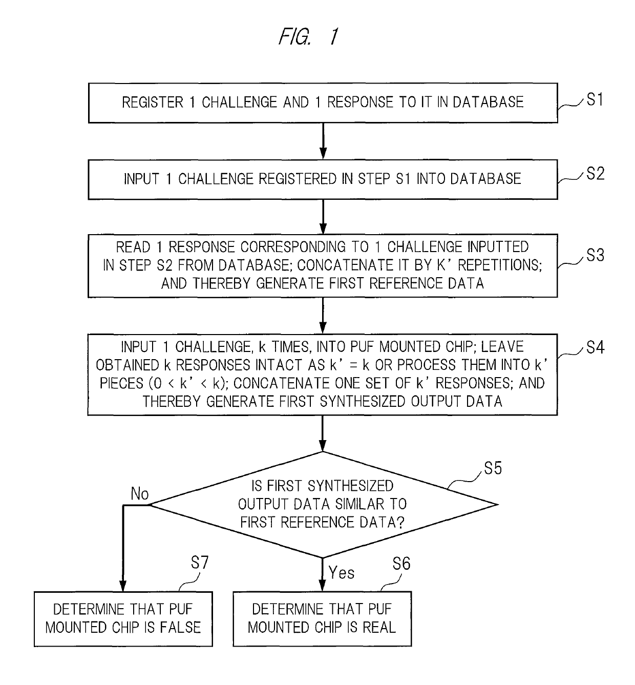
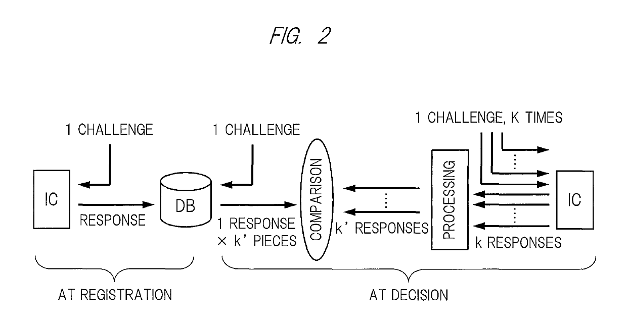
[0027]With reference to FIGS. 1 and 2, an authenticity deciding method of a PUF mounted chip in a [1, 1, 1, k, k′] mode according to a first embodiment will be described in detail.

[0028]Here, the PUF mounted chip means a semiconductor integrated circuit incorporating a PUF, and the same applies to the following.

[0029]In addition, a [1, 1, 1, k, k′] mode is one of the modes used in the authenticity decision of the PUF mounted chip (hereinafter also referred to as “usage mode”) and, as shown in FIG. 2, means a mode of: inputting one piece of input data (challenge) into a PUF mounted chip IC; registering obtained one piece of output data (response) in a database DB; and using k responses (where k is a natural number of 2 or more in the present embodiment) from the PUF mounted chip IC at a time of authenticity decision.

[0030]It should be noted that the database DB may be another means for storing a response(s) outputted from the PUF mounted chip IC, such as a hard disk and a memory circ...

second embodiment

[0041]With reference to FIGS. 3 and 4, an authenticity deciding method of a PUF mounted chip in the [1, j, j′, 1, 1] mode according to a second embodiment will be described in detail.

[0042]Here, as shown in FIG. 4, the [1, j, j′, 1, 1] mode means a usage mode of: inputting one piece of identical input data (challenge) into the PUF mounted chip IC, j times (where j is a natural number of 2 or more in the present embodiment); leaving obtained j responses intact (j′=j) or processing them into j′ pieces (0

[0043]FIG. 3 is a flowchart showing the authenticity de...

third embodiment

[0053]With reference to FIG. 5, an authenticity deciding method of a PUF mounted chip in a [1, j, j′, k, k′] mode according to a third embodiment will be described in detail.

[0054]Here, the [1, j, j′, k, k′] mode means a usage mode of: inputting one piece of identical input data (challenge) into the PUF mounted chip IC, j times (where j is a natural number of 2 or more in the present embodiment); leaving obtained j pieces of the response intact (j′=j) or processing them into j′ pieces (0

[0...


PUM


Abstract

A method and a program capable of controlling an error rate of device-specific information are provided. Provided is the method for controlling an error rate of device-specific information, including a step S1 of: inputting each of i (i is an arbitrary natural number) challenges, j times (j is an arbitrary natural number), into a PUF mounted chip; leaving j responses intact (j′=j) or processing j responses into j′ pieces (0<j′<j); and registering them in the database beforehand in association with each piece of the input data, a step S2 of inputting i challenges into the database, a step S3 of: reading j′ responses corresponding to the respective i challenges from the database; concatenating the j′ responses for each piece of the input data; further concatenating the concatenated data by k′ repetitions (0<k′≤k, and k is an arbitrary natural number, but is a natural number of 2 or more if the i and the j are both 1); obtaining the concatenated (j′×k′) responses for each piece of the input data; and further concatenating them also for different input data to obtain concatenated (i×j′×k′) responses and thereby generate reference data, a step S4 of: inputting i challenges, k times, for each challenge into the PUF mounted chip; leaving obtained k responses intact as k′=k or processing the obtained k responses into k′ pieces (0<k′<k); concatenating obtained k′ responses by j′ repetitions for each response; further concatenating them for all of the k′ responses; further concatenating concatenated (j′×k′) responses also for different input data; and obtaining concatenated (i×j′×k′) responses to generate synthesized output data, and a step S5 of deciding whether or not the synthesized output data matches the reference data (specifically, whether a Hamming distance between both data is a threshold value or less), and the method determines whether or not the error rate of the synthesized output data is within a preset range based on the decision result in step S5, and changes at least one of i, j, j′, k, and k′ to repeat steps S1 to S5 until the error rate falls within the preset range if the error rate is determined not to be within the preset range.

Description

CROSS-REFERENCE TO RELATED APPLICATIONS[0001]This application is a National Stage application of International Patent Application No. PCT / JP2015 / 073433, filed on Aug. 20, 2015, which claims priority to Japanese Patent Application Number 2014-175824, filed on Aug. 29, 2014, each of which is hereby incorporated by reference in its entirety.TECHNICAL FIELD[0002]The present invention relates to a technology for controlling an error rate of device-specific information.BACKGROUND ART[0003]Up to now, various device authentication technologies using a Physically Unclonable Function (PUF) have been devised, and for example, the following Japanese Patent Application Laid-open No. 2009-517910 discloses an authentication method using challenges / responses on a plurality of physical tokens.[0004]In addition, Japanese Patent Application Laid-open No. 2008-543060 discloses a method of performing authentication by storing the aged deterioration information of the PUF together.SUMMARY[0005]The PUF is...

Claims


Application Information

Patent Timeline
Patent Type & Authority Patents(United States)
IPC IPC(8): G06F11/00G06F11/07G09C1/00H04L9/10H04L9/32H03K19/003
CPCG06F11/0736G06F11/079G09C1/00H04L9/10H04L9/32H03K19/003G06F11/076
Inventor HORI, YOHEIKOBARA, KAZUKUNIKATASHITA, TOSHIHIROMATSUI, TOSHIHIRO
Owner NAT INST OF ADVANCED IND SCI & TECH
Why Eureka
Try Eureka