Shadow-mask-deposition system and method therefor

a shadow-mask and deposition system technology, applied in the field of thin film deposition, can solve the problems of reducing the feature resolution that can be obtained by conventional shadow-mask deposition, increasing “fauna” and many materials cannot be subjected to photolithographic chemicals without damag

Active Publication Date: 2019-08-20
EMAGIN CORP
View PDF51 Cites 0 Cited by
  • Summary
  • Abstract
  • Description
  • Claims
  • Application Information

AI Technical Summary

Benefits of technology

[0010]The present invention enables high-resolution direct deposition of a patterned layer of material on a substrate without some of the costs and disadvantages of the prior art. The present invention enables high-precision alignment of a shadow mask and substrate that are separated by only a few microns. The present invention also provides for mitigation of gravity-induced sag of a shadow mask that is supported only at its perimeter. Embodiments of the present invention are particularly well suited for applications requiring high-density patterns of material on a substrate, such as dense-pixel displays (DPD), high-definition displays, and the like.
[0012]The first chuck generates a first electrostatic force that is selectively applied to the back surface of the substrate. The first chuck is also dimensioned and arranged such that it does not project above the front surface of the substrate. In similar fashion, the second chuck generates a second electrostatic force that is selectively applied to the back surface of the shadow mask. The second chuck is also dimensioned and arranged so that it does not project above the front surface of the shadow mask. When the shadow mask and substrate are in alignment for a deposition, no part of either the first and second chuck encroaches into the three-dimensional space between the substrate and the shadow mask. As a result, the substrate and shadow mask can be positioned brought very close during deposition, thereby mitigating feathering.
[0014]In some embodiments, the second mounting surface is dimensioned and arranged to create a tensile stress in the front surface of the shadow mask that mitigates gravity-induced sag of its central region. In some such embodiments, the frame of the second chuck is shaped such that its mounting surface slopes away from top edge of the inner perimeter of the frame. As a result, when the shadow mask is mounted in the second chuck, the shadow mask becomes slightly bowed, which induces a tensile stress in the front surface of the shadow mask. In some of these embodiments, the mounting surface is curved downward from the top edge of the inner perimeter of the frame.

Problems solved by technology
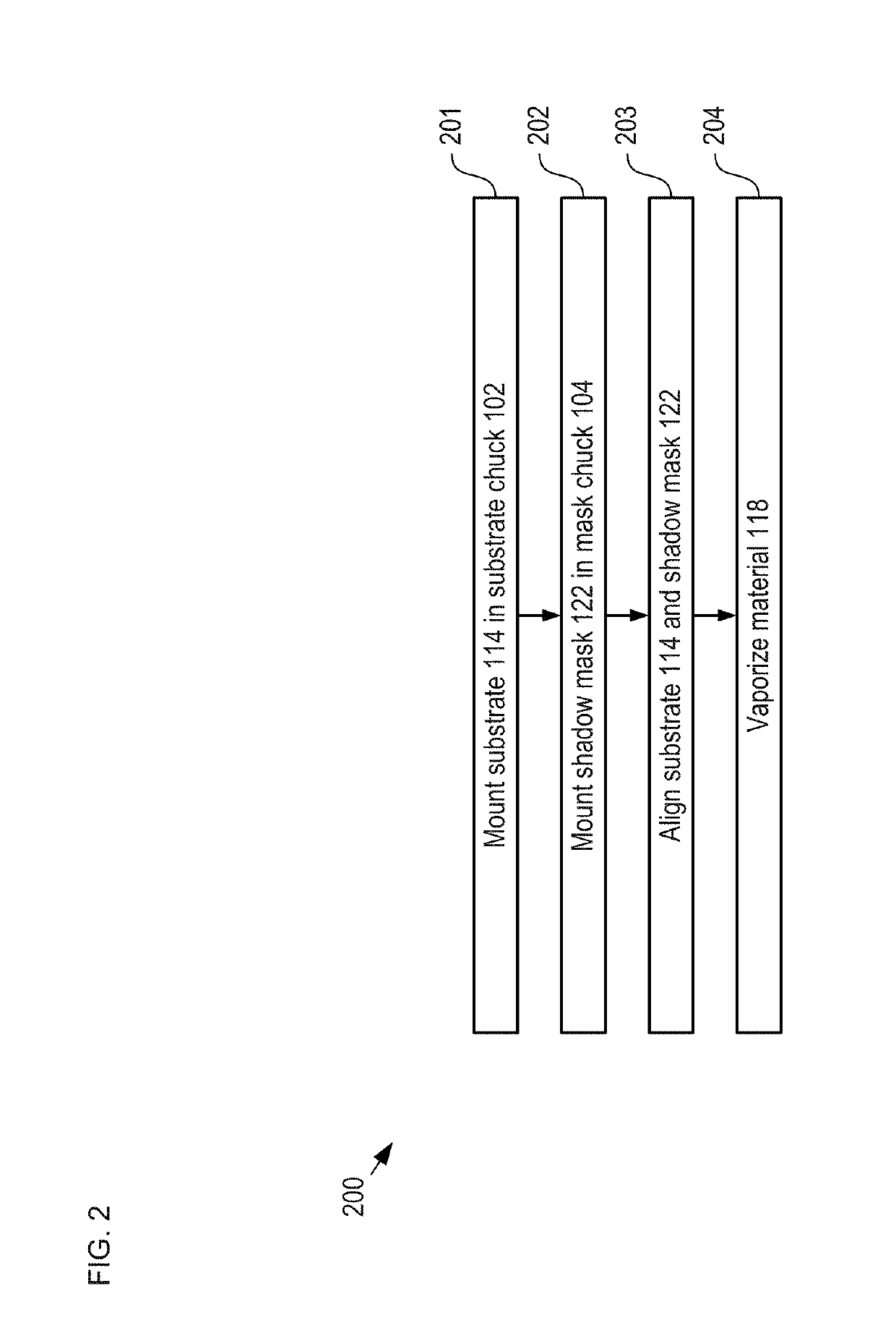
Furthermore, many materials, such as organic materials, cannot be subjected to photolithographic chemicals without damaging them, which makes depositing such materials by shadow mask a necessity.
Unfortunately, the feature resolution that can be obtained by conventional shadow-mask deposition is diminished due to the fact that the deposited material tends to spread laterally after passing through the shadow mask—referred to as “feathering.” Feathering increases with the magnitude of the separation between the substrate and the shadow mask.
Still further, any non-uniformity in this separation across the deposition area will give rise to variations on the amount of feathering.
Such non-uniformity can arise from, for example, a lack of parallelism between the substrate and shadow mask, bowing or sagging of one or both of the substrate and shadow mask, and the like.
Unfortunately, it can be difficult to hold the shadow mask and substrate close enough to avoid giving rise to significant amounts of feathering.
As a result, the center of the shadow mask can sag due to gravity, which further exacerbates feathering issues.
In practice, therefore, critical features formed by prior-art shadow-mask-based deposition techniques are typically separated by relatively large areas of open space to accommodate feathering, which limits the device density that can be obtained.
Due to feathering issues, prior-art AMOLED displays have typically been restricted to approximately 600 pixels-per-inch (ppi) or less, which is insufficient for many applications, such as near-to-eye augmented reality and virtual-reality applications.
In addition, the need for large gaps within and between the pixels gives rise to a reduced pixel fill factor, which reduces display brightness.
As a result, the current density through the organic layers must be increased to provide the desired brightness, which can negatively impact display lifetime.

Method used


Image

  • Shadow-mask-deposition system and method therefor
  • Shadow-mask-deposition system and method therefor
  • Shadow-mask-deposition system and method therefor

Examples


Embodiment Construction

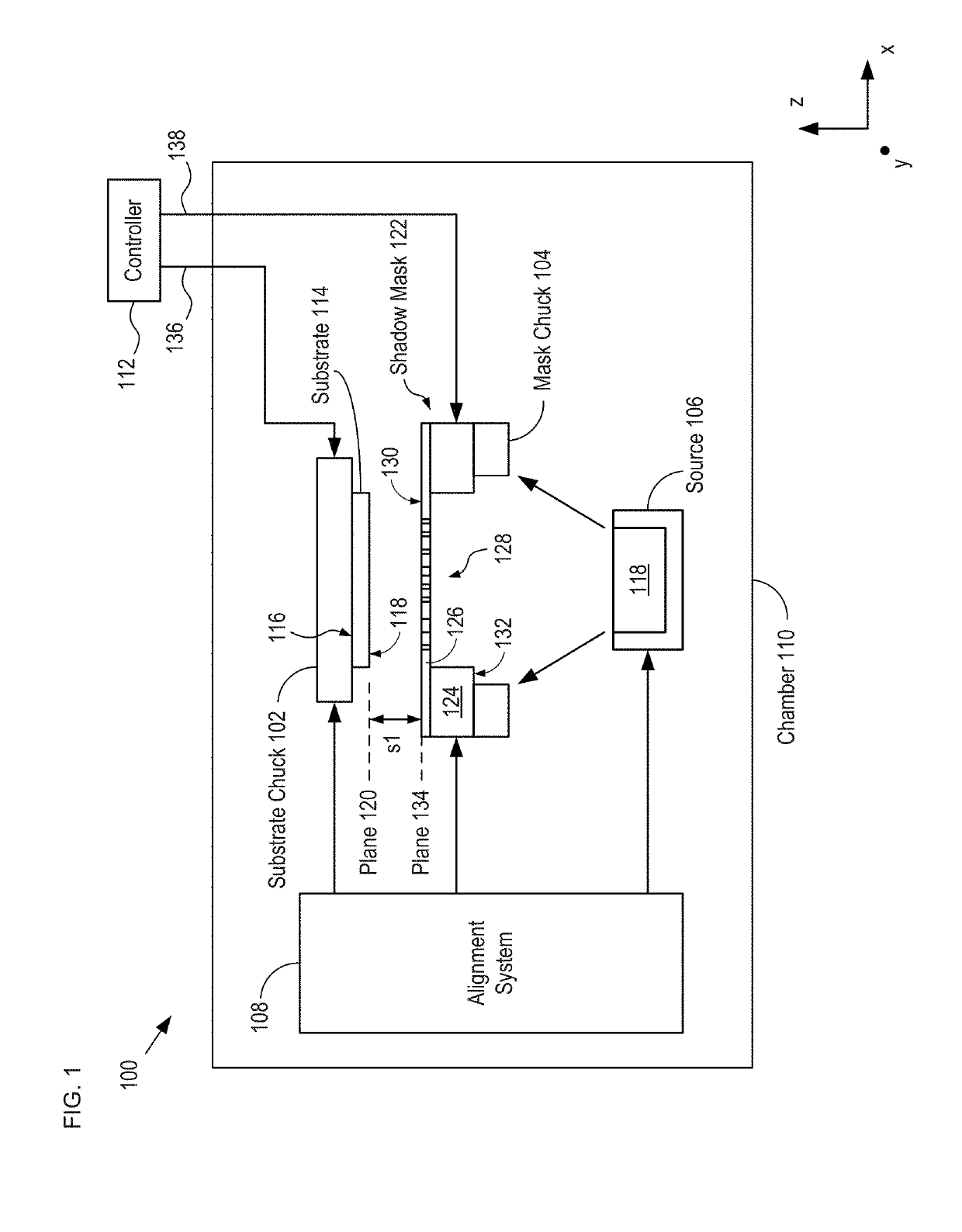
[0029]FIG. 9 depicts a schematic drawing of the salient features of a high-precision, direct-patterning deposition system in accordance with a fourth alternative embodiment of the present invention.

[0030]System 100 is described herein with respect to the deposition of a pattern of light-emitting organic material on a glass substrate as part of the fabrication of an AMOLED display. However, it will be clear to one skilled in the art, after reading this Specification, that the present invention can be directed toward the formation of directly patterned layers of virtually any thin- and thick-film material (organic or inorganic) on any of a wide range of substrates, such as semiconductor substrates (e.g., silicon, silicon carbide, germanium, etc.), ceramic substrates, metal substrates, plastic substrates, and the like. Further, although the illustrative embodiment is a thermal evaporation system, one skilled in the art will recognize, after reading this Specification, that the present ...


PUM

PropertyMeasurementUnit
thicknessaaaaaaaaaa
thicknessaaaaaaaaaa
distanceaaaaaaaaaa

Abstract

A direct-deposition system capable of forming a high-resolution pattern of material on a substrate is disclosed. Vaporized atoms from an evaporation source pass through a pattern of through-holes in a shadow mask to deposit on the substrate in the desired pattern. The shadow mask is held in a mask chuck that enables the shadow mask and substrate to be separated by a distance that can be less than ten microns. As a result, the vaporized atoms that pass through the shadow mask exhibit little or no lateral spread (i.e., feathering) after passing through its apertures and the material deposits on the substrate in a pattern that has very high fidelity with the aperture pattern of the shadow mask.

Description

STATEMENT OF RELATED CASES[0001]This case claims priority to U.S. Provisional Patent Application Ser. No. 62 / 340,793 filed on May 24, 2016, which is incorporated herein by reference.FIELD OF THE INVENTION[0002]The present invention relates to thin-film deposition in general, and, more particularly, thin-film deposition equipment.BACKGROUND OF THE INVENTION[0003]Shadow-mask-based deposition is a process by which a layer of material is deposited onto the surface of a substrate such that the desired pattern of the layer is defined during the deposition process itself. This is deposition technique is sometimes referred to as “direct patterning.”[0004]In a typical shadow-mask deposition process, the desired material is vaporized at a source that is located at a distance from the substrate, with a shadow mask positioned between them. As the vaporized atoms of the material travel toward the substrate, they pass through a set of through-holes in the shadow mask, which is positioned in conta...

Claims


Application Information

Patent Timeline
Patent Type & Authority Patents(United States)
IPC IPC(8): G03F7/20C23C14/54C23C14/50C23C14/04C23C14/30
CPCG03F7/707C23C14/042C23C14/54C23C14/50C23C14/30H01L21/6831H01L21/682C23C14/12C23C14/24H10K71/166
Inventor GHOSH, AMALKUMAR P.VAZAN, FRIDRICHANANDAN, MUNISAMYDONOGHUE, EVANKHAYRULLIN, ILYAS I.ALI, TARIQTICE, KERRY
Owner EMAGIN CORP
Why Eureka
Try Eureka