
Electrical connector having a high speed signal transmission with a high-density structure

a high-density structure and electric connector technology, applied in the direction of coupling contact members, coupling device connections, instruments, etc., can solve the problems of difficult to achieve high-speed signal transmission and hardly perform impedance matching, and achieve good high-speed signal transmission characteristics and high-density structure

Inactive Publication Date: 2019-07-30
FUJITSU COMPONENENT LTD
View PDF33 Cites 0 Cited by
  • Summary
  • Abstract
  • Description
  • Claims
  • Application Information

AI Technical Summary

Benefits of technology

[0007]According the embodiments, a connector having good high speed signal transmission characteristics with a high-density structure is provided.

Problems solved by technology

However, if the connector of Patent Document 1 is furthermore high densified, for example, cross talk between a pair of contacts for signal transmission adjacent in a lateral direction is increased so that impedance matching is hardly performed, and high speed signal transmission may be difficult actualize.

Method used


Image

  • Electrical connector having a high speed signal transmission with a high-density structure
  • Electrical connector having a high speed signal transmission with a high-density structure
  • Electrical connector having a high speed signal transmission with a high-density structure

Examples


Embodiment Construction

[0015]Hereinafter, embodiments are described with reference to drawings. It is to be noted that, in the explanation of the drawings, the same components are given the same reference numerals, and explanations are not repeated.

(Structure of Connector)

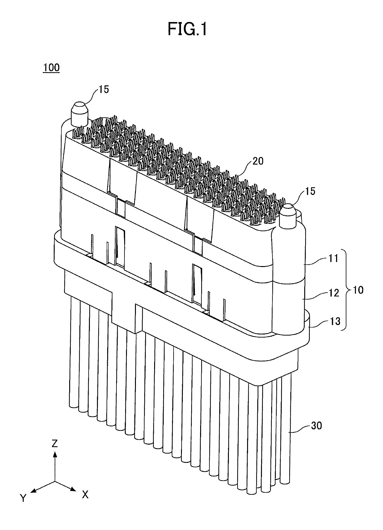
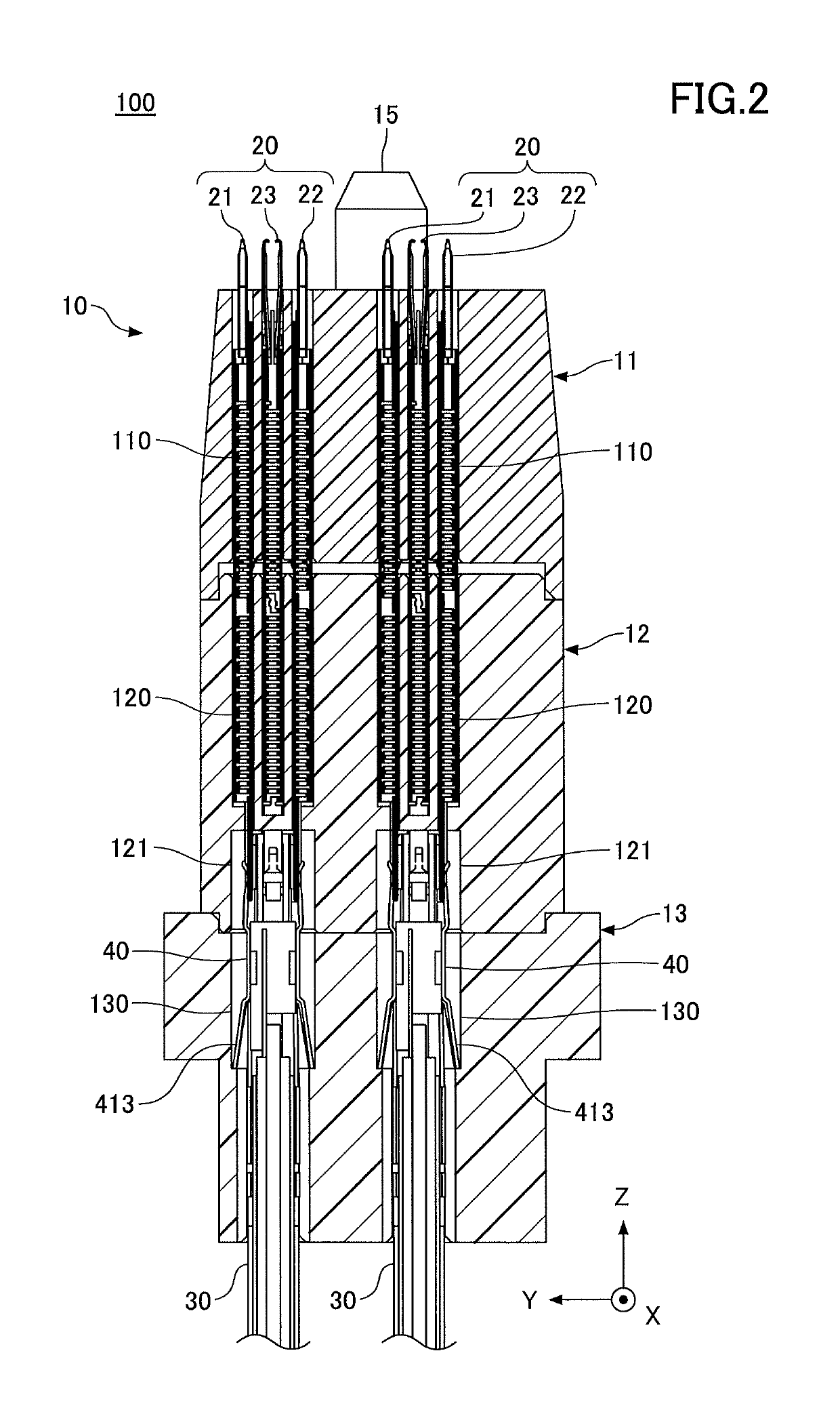
[0016]FIG. 1 is a view illustrating an example of a connector 100 of the embodiment. FIG. 2 is a cross-sectional view of the connector 100 of the embodiment. In the following drawings, an X direction is a longitudinal direction of the connector 100, a Y direction is a shorter direction of the connector 100, and a Z direction is a height direction of the connector 100.

[0017]As illustrated in FIG. 1 and FIG. 2, the connector 100 includes a housing 10 and a plurality of contacts (contact sets) 20, and coaxial cables 30 are connected to one end of the contacts 20, respectively.

[0018]The housing 10 includes a first housing 11, a second housing 12 and a third housing 13, and holds the contacts 20 and the coaxial cables 30. The first housing 11...


PUM


Abstract

A connector includes multiple contact sets that are aligned. Each of the contact sets includes a signal contact for signal transmission and multiple ground contacts. The ground contacts include respective shield portions. The ground contacts are provided around the signal contact in such a manner as to surround the signal contact by the respective shield portions.

Description

BACKGROUND OF THE INVENTION1. Field of the Invention[0001]The present invention relates to a connector.2. Description of the Related Art[0002]It is required for a connector that is connected to a printed circuit board or the like, for example, to actualize high-density and high speed signal transmission in accordance with a downsizing of a device, increasing of sent data volume and the like. A ground contact may be provided to reduce cross talk between signal contacts, noise and the like in such a high-density connector.[0003]As such a high-density connector, a structure is known that includes a plurality of contacts aligned in a zig-zag manner, in which two adjacent front and back lines are used as a pair of contacts for signal transmission, and lines provided front and back of the pair of contacts for signal transmission are used as ground contact lines (see Patent Document 1, for example).PATENT DOCUMENT[Patent Document 1] Japanese Laid-open Patent Publication No. 2009-87656[0004...

Claims


Application Information

Patent Timeline
Patent Type & Authority Patents(United States)
IPC IPC(8): H01R13/24H01R12/79H01R13/6471G01R1/067H01R13/6585H01R9/05H01R12/71G01R3/00H01R107/00
CPCH01R13/6471G01R1/06722H01R9/0515H01R12/79H01R13/6585H01R2107/00G01R3/00H01R12/716H01R13/2421
Inventor KONDO, TAKAHIROTANAKA, TETSUGAKU
Owner FUJITSU COMPONENENT LTD
Learn More