
Printed circuit board assembly and assembling method thereof

a technology of printed circuit board and assembly method, which is applied in the direction of printed circuit aspects, printed circuit non-printed electric components association, electrical apparatus construction details, etc., can solve the problems of affecting the stability of products, affecting the installation location of plug-in electronic devices on printed circuit boards, and many electronic devices generating large amounts of heat during their operation. , to achieve the effect of dissipating heat, reducing the amount of available space and high density

Active Publication Date: 2019-05-16
DELTA ELECTRONICS INC
View PDF3 Cites 0 Cited by
  • Summary
  • Abstract
  • Description
  • Claims
  • Application Information

AI Technical Summary

Benefits of technology

The present invention provides a printed circuit board assembly and an assembling method thereof. It uses a holder to attach the electronic device of the printed circuit board to the heat-dissipation device for effective heat-dissipation and maintaining the electronic device at a fixed position. The holder is easy to assemble and provides sufficient strength to support the electronic device. This eliminates stress from the pins of the electronic device and allows unrestricted arrangement of other electronic components. The holder also integrates space between the printed circuit board and the heat-dissipation device, improving space utilization. Overall, this invention achieves both efficient heat-dissipation and high-density structure.

Problems solved by technology

With the increasing demand for the electronic products with the high power density, many electronic devices generate large amounts of heat during their operation.
However, since the plug-in electronic device has been soldered on the printed circuit board, if the electronic device is further fastened through the resilient fastening sheet and the screw, it is easy to generate a tensile stress at the solder joints between the pins of the electronic device and the printed circuit board or damage the structural body of the electronic device, and thus affect the stability of the product.
In addition, in order to perform the fastening process of the resilient fastening sheet and the screw, the installation location of the plug-in electronic device on the printed circuit board is further limited.
For example, if the electronic device is horizontally plugged on the printed circuit board, it will occupy the layout area of the printed circuit board for other components, which results in the drawbacks of reducing the available utilization area of the printed circuit board, increasing the size of the product and decreasing the competitiveness of the product.
Otherwise they cannot be assembled and produced.
Thus, the space between the printed circuit board and the heat-dissipation device cannot be utilized easily, which also results in that the structural density of the system is reduced and the competitiveness of the product is decreased.

Method used


Image

  • Printed circuit board assembly and assembling method thereof
  • Printed circuit board assembly and assembling method thereof
  • Printed circuit board assembly and assembling method thereof

Examples


Embodiment Construction

[0025]The present invention will now be described more specifically with reference to the following embodiments. It is to be noted that the following descriptions of preferred embodiments of this invention are presented herein for purpose of illustration and description only. It is not intended to be exhaustive or to be limited to the precise form disclosed.

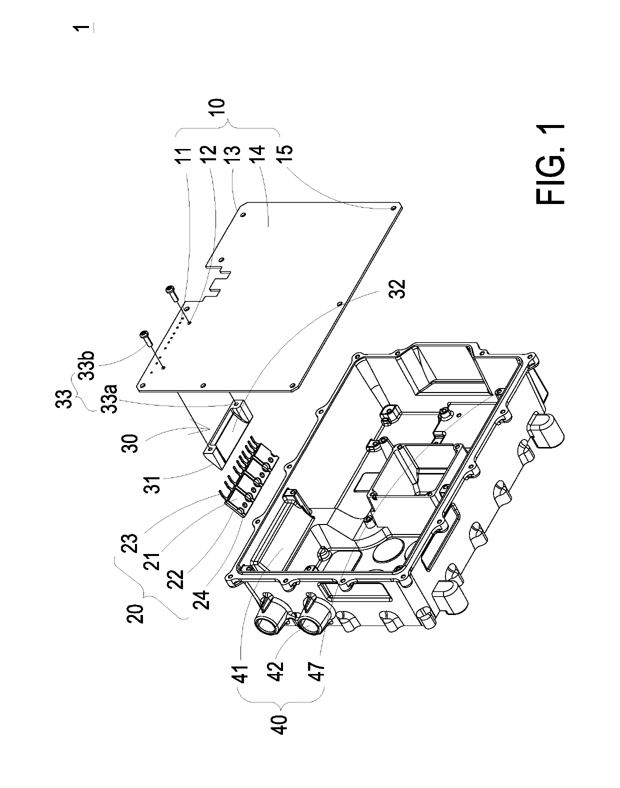
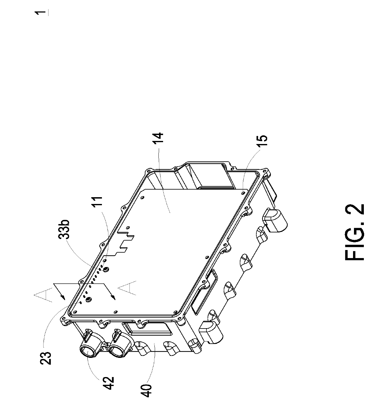
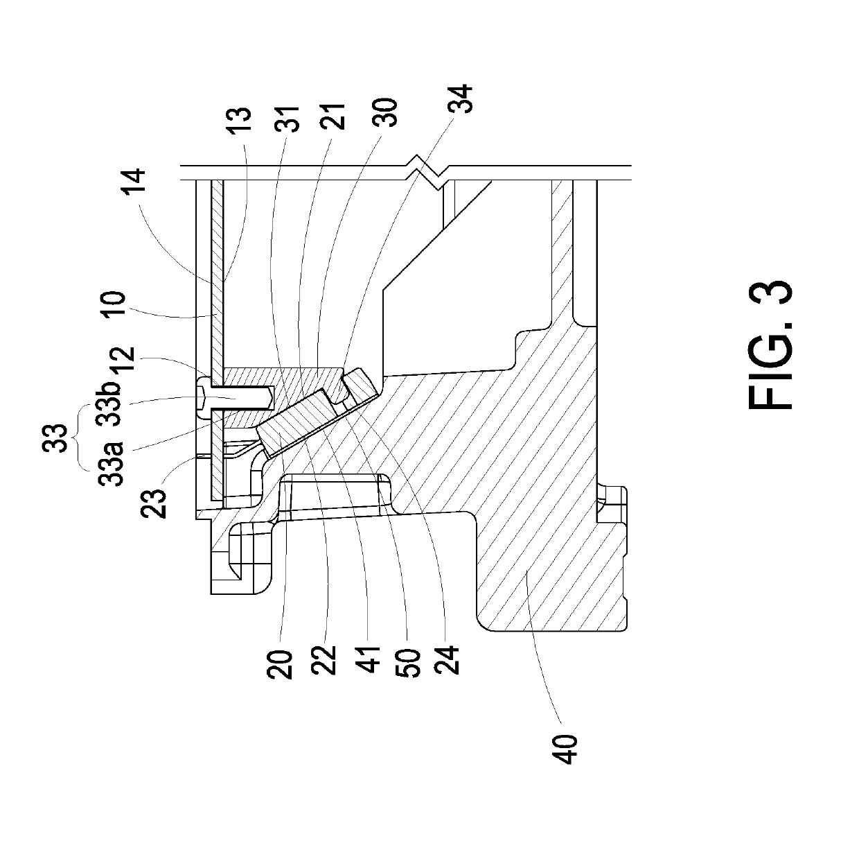
[0026]FIG. 1 is an exploded view illustrating a printed circuit board assembly according to a first preferred embodiment of the present invention, FIG. 2 is a perspective structural view illustrating the printed circuit board assembly according to the first preferred embodiment of the present invention, and FIG. 3 is a cross-sectional view taken along line A-A of FIG. 2 and illustrating the printed circuit board assembly thereof. As shown in FIGS. 1 to 3, the printed circuit board assembly (hereafter referred as the assembly) 1 includes a printed circuit board 10, at least one electronic device 20, a holder 30 and a heat-dissipat...


PUM


Abstract

A printed circuit board assembly includes a printed circuit board, at least one electronic device, a holder and a heat-dissipation device. The printed circuit board includes at least one first through hole. The electronic device includes a first surface, a second surface and at least one pin. The first surface and the second surface are opposite to each other, and the pin passes through the first through hole of the printed circuit board and is inserted on the printed circuit board. The holder is secured to the printed circuit board and disposed between the printed circuit board and the electronic device. The holder includes a pushing piece configured to provide a supporting surface to sustain the first surface of the electronic device. The heat-dissipation device includes a heat-dissipation surface thermally coupled with the second surface of the electronic device.

Description

CROSS-REFERENCE TO RELATED APPLICATION[0001]This application is a Continuation Application of U.S. patent application Ser. No. 15 / 667,964 filed on Aug. 3, 2017, and entitled “PRINTED CIRCUIT BOARD ASSEMBLY AND ASSEMBLING METHOD THEREOF”, the entirety of which is hereby incorporated by reference for all purposes.FIELD OF THE INVENTION[0002]The present invention relates to an assembly, and more particularly to a printed circuit board assembly and an assembling method thereof.BACKGROUND OF THE INVENTION[0003]With the increasing demand for the electronic products with the high power density, many electronic devices generate large amounts of heat during their operation. Therefore, an effective cooling system must be arranged therewith to dissipate the heat so that the overall performance is not affected by the heat accumulated therein. On the other hand, in order to meet the requirements of the high power density and the heat-dissipation, such electronic device is usually disposed on the...

Claims


Application Information

Patent Timeline
Patent Type & Authority Applications(United States)
IPC IPC(8): H05K1/11H05K3/30H05K1/18H05K7/20
CPCH05K1/115H05K3/306H05K1/181H05K7/20H05K3/303H05K3/301H05K3/3447H05K1/0203H05K1/0209H05K2201/066H05K7/20445H05K7/209H05K1/184
Inventor KUO, CHING-CHIHSIEH, YI-HWA
Owner DELTA ELECTRONICS INC
Learn More