
Shield for zero-turn mowers

a mower and blade technology, applied in the field of zero-turn mowers, can solve the problems of affecting the operation of operators, affecting the cleaning effect of operators, etc., and achieve the effect of convenient cleaning, easy mounting and removal

Active Publication Date: 2019-07-23
HARRIS WILLIAM R
View PDF9 Cites 3 Cited by
  • Summary
  • Abstract
  • Description
  • Claims
  • Application Information

AI Technical Summary

Benefits of technology

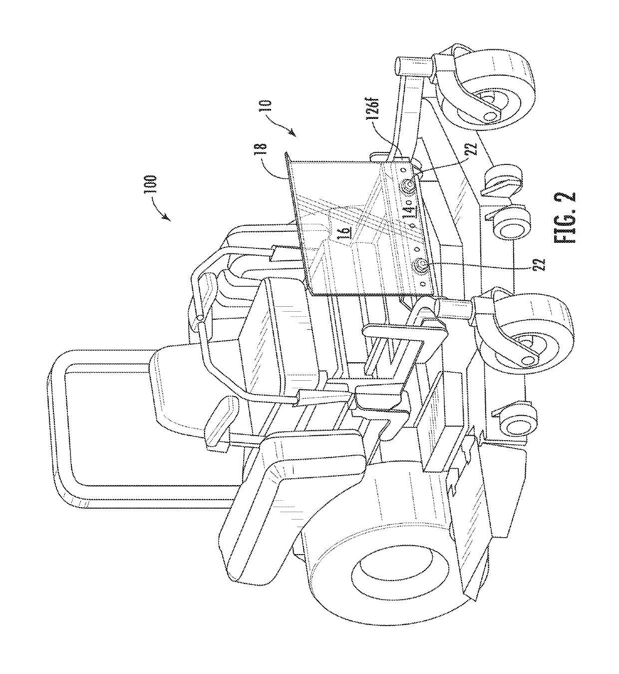
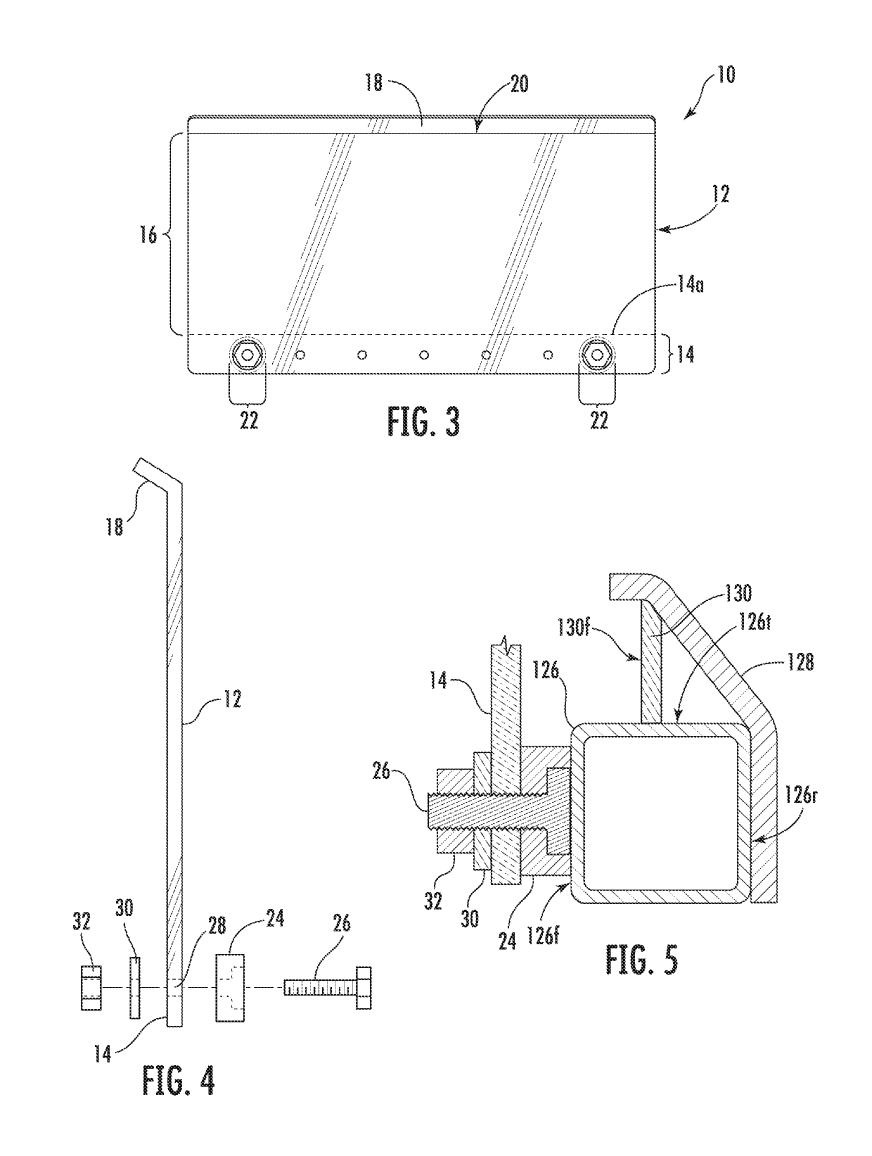
The subject invention is an accessory apparatus for zero-turn mowers that shields the operator from airborne insects and debris while mowing. The apparatus is magnetically mounted, easy to mount and dismount, less likely to cause injury, and can be made from smooth, easily cleanable materials. It is also easy to mount and remove for cleaning without being disassembled. The invention is cost-effective to manufacture and sale to the consuming public.

Problems solved by technology

Although z-turn mowers possess many advantages over riding mowers which are front engine driven, they do suffer from one important disadvantage.
As a result, the operator often becomes covered with the debris and insects.
This makes it impractical for operators to wear shorts when mowing which would otherwise be a desirable practice, particularly in warm or hot temperatures which are typically associated with the peak grass growing (and mowing) season.
Because the panel projects forwardly past the cutting deck it is susceptible to damage such as may occur when the front of the mower comes into close contact with trees, fencing and the like.
Moreover, although the center portion of the shield is transparent, the relatively large framing members of the apparatus obstruct the operator's view immediately forward of the mower which is arguably the most important area to have clearly visible.
Additionally, the shield is of a fixed width and, therefore, can only be installed between framing members spaced at a specific distance.
Because of its size, the apparatus is susceptible to coming into contact with tree branches, hedges and the like.
It will also, to a degree, cut down on ventilation which is certainly undesirable in hot conditions.

Method used


Image

  • Shield for zero-turn mowers
  • Shield for zero-turn mowers
  • Shield for zero-turn mowers

Examples


Embodiment Construction

[0030]At the outset, it should be clearly understood that like reference numerals are intended to identify the same structural elements, portions or surfaces consistently throughout the several drawings figures, as such elements, portions or surfaces may be further described or explained by the entire written specification, of which this detailed description is an integral part. Unless otherwise indicated, the drawings are intended to be read (e.g., cross-hatching, arrangement of parts, proportion, degree, etc.) together with the specification, and are to be considered a portion of the entire written description of this invention. The figures provided herewith are for explanation purposes to persons ordinarily skilled in the art and that the drawings are not necessarily drawn to scale.

[0031]In addition, as used in the following description, any reference to terms of orientation such as “horizontal”, “vertical”, “front”, “rear”, “left”, “right”, “up”, “down”, “inward” or “outward”, “...


PUM


Abstract

A shielding apparatus for mounting on zero-turn type mowers of the variety having a horizontal cross-member forward of an operator seat and disposed between a pair of longitudinal frame members supporting a cutting deck, the shielding apparatus being comprised of a panel having a lower mount portion and an upper shield portion, the mount portion being mountable to the cross-member such that said shield portion is oriented vertically, perpendicular to the cutting deck. The shield portion is sized, shaped and oriented to substantially blocks debris and insects expelled forwardly and upwardly from beneath the cutting deck of the mower from coming into contact with an operator of the mower. Embodiments of the subject shielding apparatus are adapted for magnetic mounting to the mower.

Description

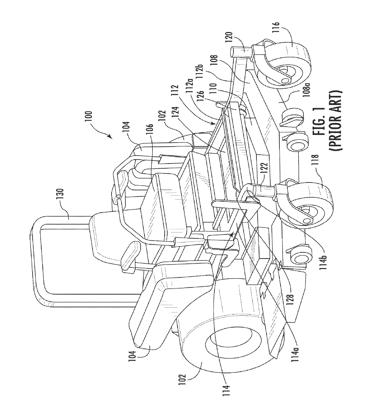
FIELD OF THE INVENTION[0001]The subject invention relates to zero-turn lawn mowers, generally, and to an apparatus for shielding operators of such mowers from airborne debris and insects, in particular.BACKGROUND OF THE INVENTION[0002]A zero-turn lawn mower (often referred to colloquially as a “z-turn” or “ZTR” mower) is a rear engine mounted riding lawn mower with a turning radius that is effectively zero. Zero-turn mowers have become very popular for both residential and commercial use. Three primary reasons for this popularity are the high degree of forward visibility afforded by virtue of having the engine mounted in the rear, and their superior maneuverability and high cutting rates relative to conventional riding mowers. These attributes can together reduce mowing time by up to 50%.[0003]Although z-turn mowers possess many advantages over riding mowers which are front engine driven, they do suffer from one important disadvantage. Because the operator sits in front of the engin...

Claims


Application Information

Patent Timeline
IPC IPC(8): B60J1/02A01D34/00A01D34/64A01D101/00
CPCB60J1/025A01D34/001A01D34/64A01D2101/00A01D34/81
Inventor HARRIS, WILLIAM R.
Owner HARRIS WILLIAM R
Learn More