
Conveyor apparatus and commodity inspecting equipment utilizing the same

Inactive Publication Date: 2005-10-25
ISHIDA CO LTD
View PDF18 Cites 18 Cited by
  • Summary
  • Abstract
  • Description
  • Claims
  • Application Information

AI Technical Summary

Benefits of technology

[0019]Also, since it is not the structure in which the support member is provided in the housing and the conveyor apparatus is supported by the housing, there is no need to assembly various members on a surface of the housing. Accordingly, the housing can have a surface neat in finish and with neither projection nor indentation and, therefore, any possible deposition, stay and biting of the dregs of the article to be weighted can be suppressed. Also, a cleaning work is easy to perform, resulting in increase of a cleaning capability.
[0073]Again, in the weighing conveyor according to the ninth aspect, when the drive transmission mechanism is to be disposed between the conveyor apparatus, which has been disposed with its weight balanced in the transport widthwise direction relative to the load detector, and the drive source arranged at a location substantially level with the load detector in the transport widthwise direction, the drive transmission mechanism is so arranged as to extend between the position substantially level with the load detector in the transport widthwise direction and the position either leftwards or rightwards thereof or as to extend in a direction parallel to the transport widthwise direction with the load detector intervening therebetween. Accordingly, the weights in the transport widthwise direction of the conveyor apparatus are well balanced and the center of gravity of the conveyor apparatus can be brought close to the center of moment of the load detector with respect to the transport widthwise direction.

Problems solved by technology

A relation in position between the conveyor apparatus and the housing is such that since a space above the conveyor apparatus is required to be open wide in view of articles to be weighed being placed on the conveyor apparatus and since measurements would result in an error when foreign matter falls onto the conveyor apparatus, the conveyor apparatus is generally disposed immediately above the housing or in side by side fashion relative to the housing.
However, if the top surface or side surface of the housing has the opening through which the support member extends and the diaphragm or the like, the dregs deposited thereon tend to easily accumulate, resulting in proliferation of unwanted bacteria to such an extent as to result in degradation of sanitary conditions and also to perforation in the diaphragm as a result of the dregs or the like having been bitten.
Also, even where a cleaning work is regularly performed using a cleansing liquid or the like, a surface structure of the top surface or side surface of the housing is complicated, resulting in the cleaning capability of the opening, diaphragm and their surroundings being reduced.
Accordingly, in addition to the weight of the conveyor apparatus, the weight of the support member or the weight of a drive transmission mechanism, such as the drive motor, the drive transmitting belt and pulleys or the like, the weight of the housing is loaded on the load cell as a tare weight and, therefore, the tare weight tends to become heavy, accompanied by reduction in natural frequency of a measurement system of the weighing conveyor, which in turn results in lowering of the weighing accuracy.
Accordingly, there has been a problem in that a weight signal outputted from the load cell contains noises and, therefore, the weighing accuracy tends to be lowered.
Since the up and down direction lie in the direction in which the elastic element of the load cell displaces during the load detection, a change in load brought about by the vibrations is detected by the load cell, with the consequence that the weight signal from the load cell contains noises, resulting in reduction of the weighing accuracy.
The more considerable the fluctuation of the drive shaft being driven, the more considerable the vibration brought about by the effect of the centrifugal force.
In other words, in the event that the mass of the rotating element is in an unbalanced state with respect to the center of rotation thereof or the drive shaft fluctuate about the longitudinal axis thereof during rotation thereof, the noises tend to become paramount.
However, with the known technique, plural load cells are required and, accordingly, not only does a hardware aspect become complicated, but also a software aspect of a signal processing for processing the weight signal becomes complicated, resulting in disadvantages in terms of cost.
Accordingly, since the natural frequency of the weighing conveyor decreases as a result of increase of the weight of the conveyor apparatus, that is, the tare weight, a low pass filter having a high cutoff frequency, for example, cannot be used.
For this reason, the response of the filter does not increase so much and a filter processing time does not decrease so much, and accordingly, a high speed weighing operation is hampered.

Method used


Image

  • Conveyor apparatus and commodity inspecting equipment utilizing the same
  • Conveyor apparatus and commodity inspecting equipment utilizing the same
  • Conveyor apparatus and commodity inspecting equipment utilizing the same

Examples


Embodiment Construction

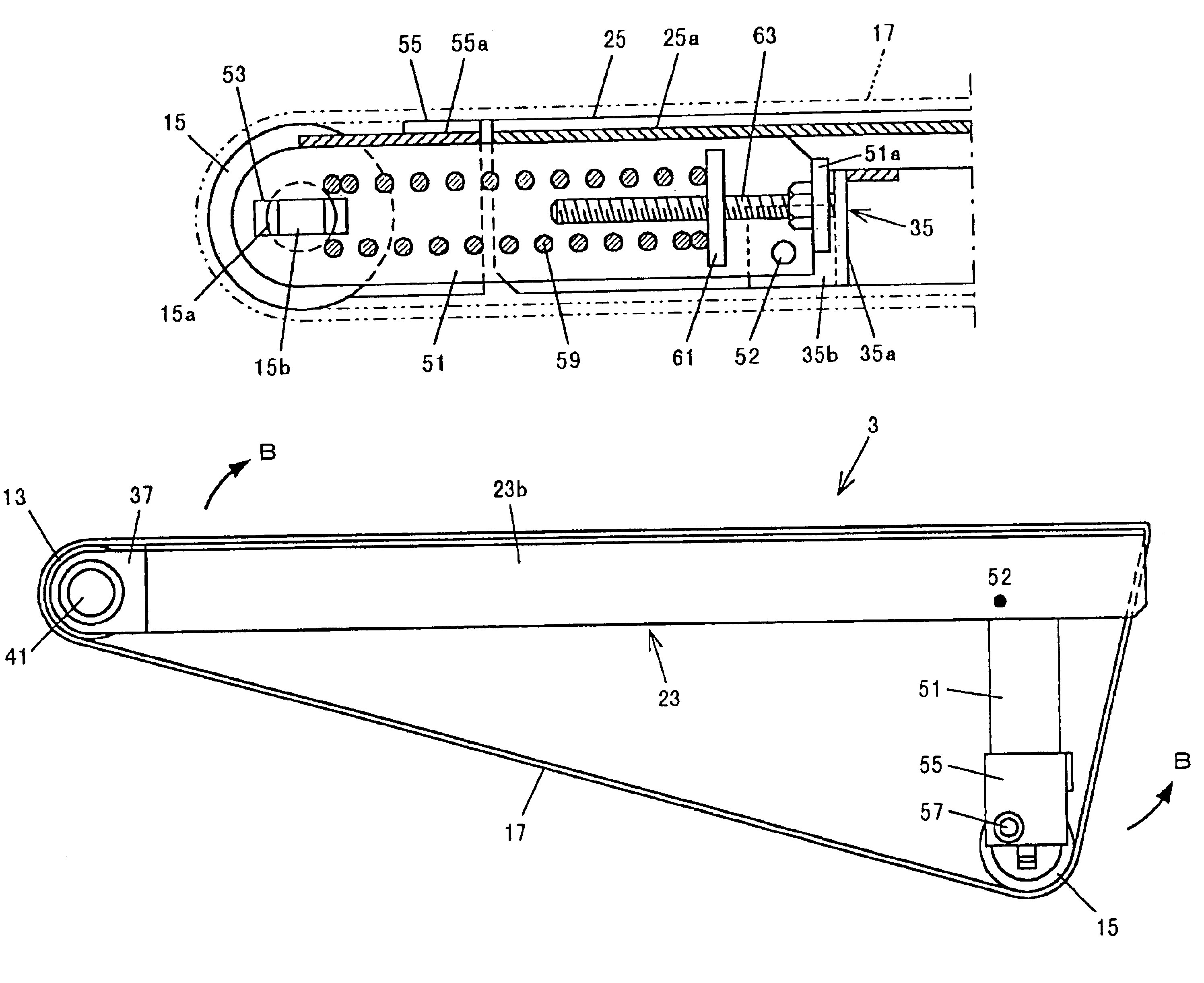
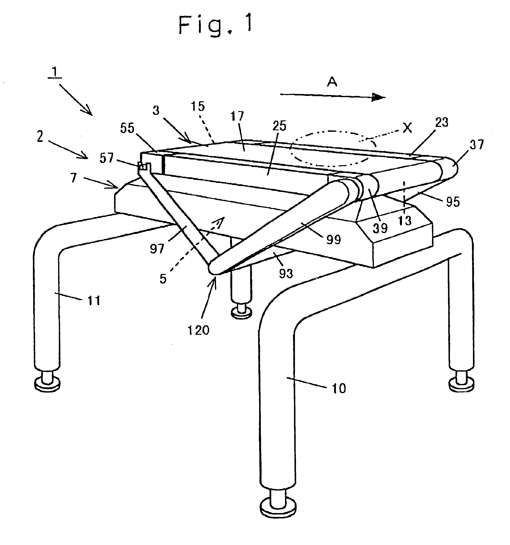
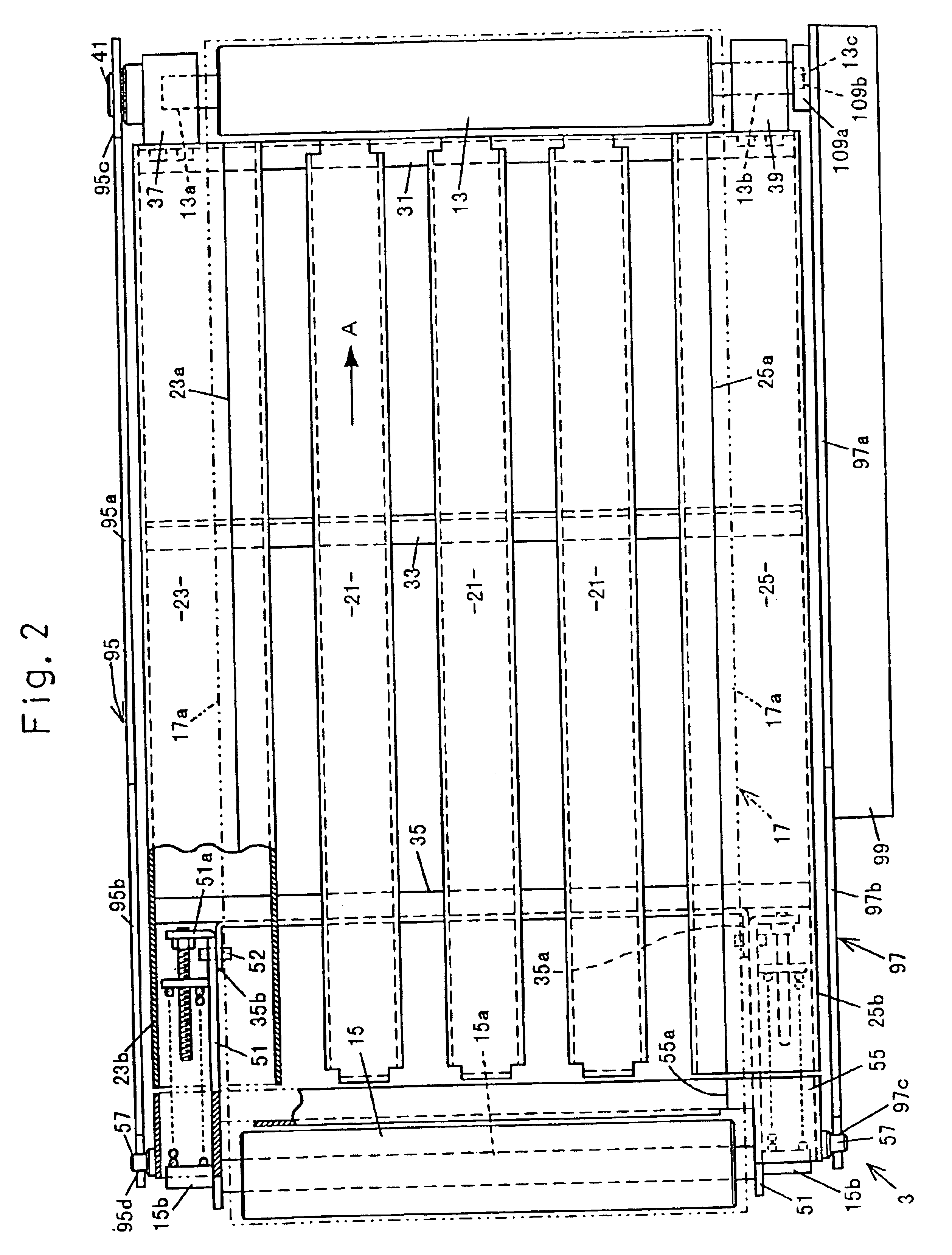
[0097]Hereinafter, a weighing conveyor according to a first aspect of the present invention will be described. In an embodiment shown in FIG. 1, a weighing conveyor 2 is applied to a weight checker 1 which is a weighing apparatus. This weighing conveyor 2 includes a conveyor apparatus 3 of a flat belt type, and a housing 7 accommodating therein a load cell 5 serving as a load detector. The housing 7 is fixed on a pair of front and rear leg members 10 and 11. The weighing conveyor 2 is disposed at a tail end of a production line and is operable, for example, to measure, one at a time, the weight of bagged products X which are articles to be weighed and which are supplied from a bagging and packaging machine (not shown), while the bagged products X are successively transported by the conveyor apparatus 3 in a direction shown by the arrow A, and then to deliver the bagged products X successively onto, for example, a metal detector (not shown) or the like.

[0098]As shown in FIG. 2, the c...


PUM


Abstract

A weighing conveyor having an increased weighing accuracy. This conveyor includes a conveyor apparatus 3 for transporting an article X to be weighed, a load detector 5 for detecting the weight of the article X to be weighed, and a housing 7 for accommodating the load detector 5, in which a fixed end 5b of the load detector is connected with the housing 7 and a free end 5c thereof is connected with a support member 120 for supporting the conveyor apparatus 3, and the support member 120 protrudes outwardly of the housing 7 from a bottom surface thereof.

Description

[0001]This application is a division of Ser. No. 10 / 009,832 filed Dec. 17, 2001 now U.S. Pat. No. 6,803,529, which is a 371 of PCT / JP01 / 03914 filed May 5, 2001.FIELD OF THE INVENTION[0002]The present invention relates to a conveyor apparatus and a commodity inspecting equipment equipped with such conveyor apparatus.BACKGROUND ART[0003]A commodity inspecting equipment such as a weighing conveyor for, while articles are successively transported by a conveyor apparatus in a production line, measuring the weight thereof includes, for example, a conveyor apparatus of a type in which an endless flat belt or the like is trained as a transport belt between a pair of rollers supported by a frame. One of the roller is a drive roller to which a driving force from a drive source such as a motor for moving the transport belt, and as a belt for transmission of the driving force an endless belt or the like is trained between a pulley, mounted coaxially on the drive roller, and a pulley mounted on ...

Claims


Application Information

Patent Timeline
IPC IPC(8): B65G23/00B65G23/32B65G15/00G01G11/00G01G11/04B65G23/44
CPCB65G15/00B65G23/32B65G23/44G01G11/00G01G11/04B65G2201/06G01G21/28
Inventor TAKAHASHI, ATSUSHI
Owner ISHIDA CO LTD
Learn More