PIP trace heating connection assembly

a heating connection and assembly technology, applied in the direction of heating elements, lighting and heating apparatus, coupling device connections, etc., can solve the problems of time-consuming process, risk of hydrate plugging and wax formation, etc., and achieve the effect of quick assembly and quick method of joining

Active Publication Date: 2019-07-16
TECH FRANCE SA
View PDF30 Cites 2 Cited by
  • Summary
  • Abstract
  • Description
  • Claims
  • Application Information

AI Technical Summary

Benefits of technology

The objective of this patent is to develop a faster way to join heating cables during the manufacturing process of ETH-PIP. The technical effect of this patent is to reduce the time required for the joining process.

Problems solved by technology

However, fluids circulating along deep-water or long tie-back flowlines may experience a significant temperature drop, leading to the risk of hydrate plugging and wax formation, especially in oil and gas flows.
This is a time consuming process, generally taking at least 4 hours per cable.

Method used


Image

  • PIP trace heating connection assembly
  • PIP trace heating connection assembly
  • PIP trace heating connection assembly

Examples


Embodiment Construction

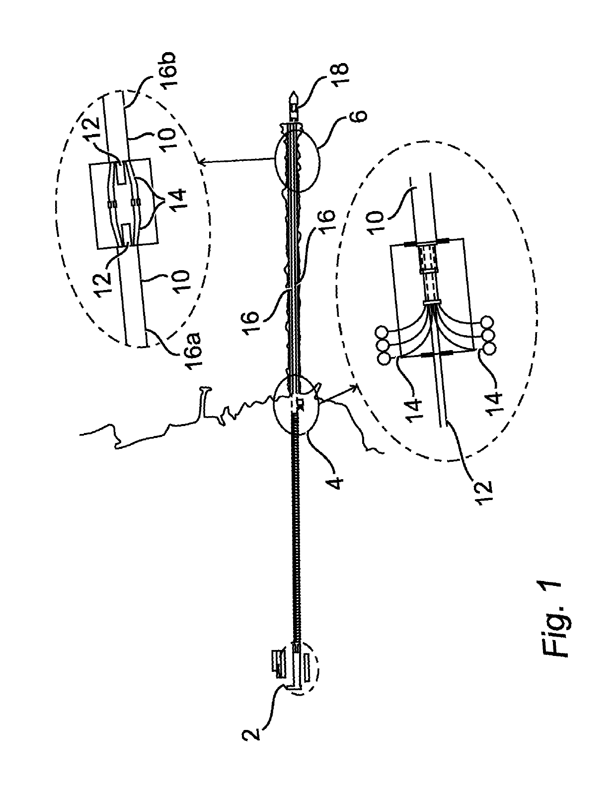
[0082]FIG. 1 is a schematic plan view of a typical spoolbase layout for a PIP construction process, and for reeling onto a lay vessel. From left to right, there is a fabrication building 2 with initial welding stations to form the initial pipe lengths towards a first tie-in station 4, where trace heating cables 14 are added from cable reels around the flowline 12, and insulation is also added along with spacers; prior to insertion of the combination into the outer or carrier pipe 10 and towards the reel lay vessel 18.

[0083]Insert G is an enlarged view of a stalk tie-in station 6 for the joining of a newly formed PIP stalk 16a to an existing PIP stalk 16b already mostly reeled onto the vessel 18. Conventionally at the station 6, the two flowlines 12 are first welded together, and then the heating cables 14 are spliced directly together, to join them and so form a continuous electrical connection along the PIP pipeline. Insulation and spacers are then added around the spliced heating ...


PUM


Abstract

A PIP Trace Heating Connection Assembly A pipe-in-pipe (PIP) trace heating connection assembly in the annulus of a PIP pipeline comprising at least first and second conjoined PIP stalks having inner and outer pipes and the annulus thereinbetween, the first PIP stalk having a first trace heating cable (22) located along its inner pipe, and the second PIP stalk having a second trace heating cable (24) located along its inner pipe, the first and second heating cables have cable ends and heating cable terminals on the cable ends, and a flexible intermediate connecting cable (40) having first and second intermediate terminals secured to, the heating cable terminals of the first and second trace heating cables respectively to form a secured electrical pathway between the first and second trace heating cables. In this way, securing the heating cable terminals with the intermediate connecting cable significantly reduces the time required to form a secured electrical pathway between the trace heating cables of each PIP stalk.

Description

CROSS-REFERENCE TO RELATED APPLICATIONS[0001]The present application is a 35 U.S.C. §§ 371 national phase conversion of PCT / IB2014 / 003132, filed Dec. 19, 2014, which claims priority to United Kingdom Patent Application No. 1322696.4, filed Dec. 20, 2013, the contents of which are incorporated herein by reference. The PCT International Application was published in the English language.TECHNICAL FIELD OF THE INVENTION[0002]The present invention relates to a trace heating connection assembly for a multi-pipe pipeline such as a pipe-in-pipe (PIP) pipeline, a PIP pipeline having such an assembly, a flexible intermediate connecting cable, and to a method of connecting trace heating cables of PIP stalks during manufacture.BACKGROUND OF THE INVENTION[0003]Pipe-in-pipe pipelines, also known as PIP pipelines, are well known in the art, and generally comprise, with reference to the accompanying prior art FIG. 1, an outer pipe 10 (or “carrier pipe”) and a usually concentric or co-axial inner pi...

Claims


Application Information

Patent Timeline
Patent Type & Authority Patents(United States)
IPC IPC(8): F24H1/10F16L53/38H05B3/56H05B3/06F16L39/00B23P19/00H01R4/18H01R13/622
CPCB23P19/00F16L39/005F16L53/38H05B3/56H05B3/06H05B2214/03H01R4/183H01R13/622F16L1/26
Inventor TKACZYK, TOMASZCHALMERS, MARTIN
Owner TECH FRANCE SA
Why Eureka
Try Eureka