
Fire extinguisher with internal mixing and external gas cartridge

a technology of gas cartridges and fire extinguishers, applied in fire rescue and other directions, can solve the problems of gas concentration and exposure duration, and achieve the effect of minimal training and higher service level

Active Publication Date: 2019-07-16
RUSOH INC
View PDF42 Cites 1 Cited by
  • Summary
  • Abstract
  • Description
  • Claims
  • Application Information

AI Technical Summary

Benefits of technology

Enables efficient and complete discharge of fire suppressant media, reduces maintenance needs, enhances security by allowing untrained users to operate and maintain the extinguisher, and prevents material degradation, with experimental results showing nearly 100% CO2 discharge even at -40°C.

Problems solved by technology

Polycarbonate is a cost effective candidate for a transparent cylinder, however when polycarbonate is in intimate contact with ammonia gas, material degradation will occur at a rate related to the gas concentration and exposure duration.

Method used


Image

  • Fire extinguisher with internal mixing and external gas cartridge
  • Fire extinguisher with internal mixing and external gas cartridge
  • Fire extinguisher with internal mixing and external gas cartridge

Examples


Embodiment Construction

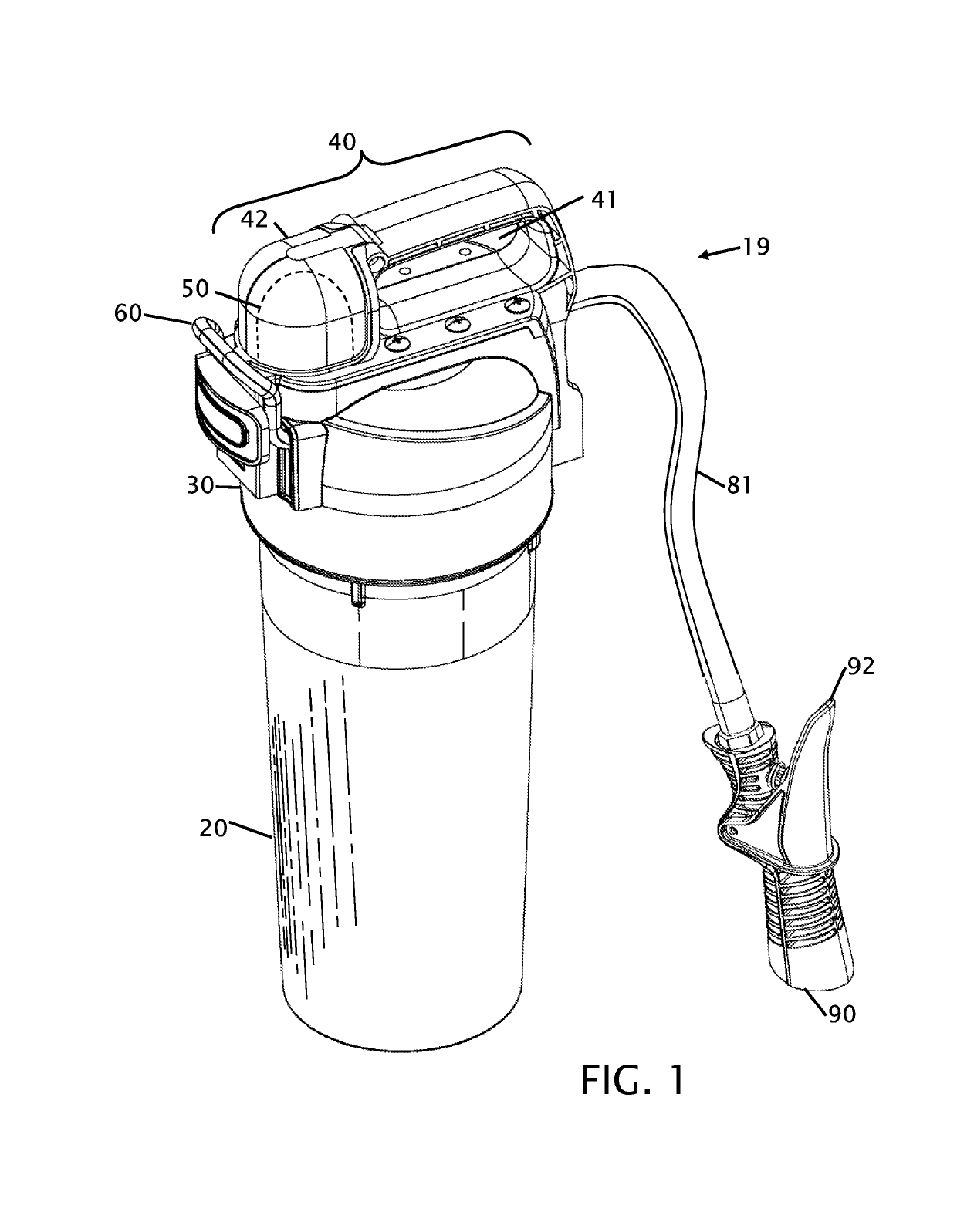
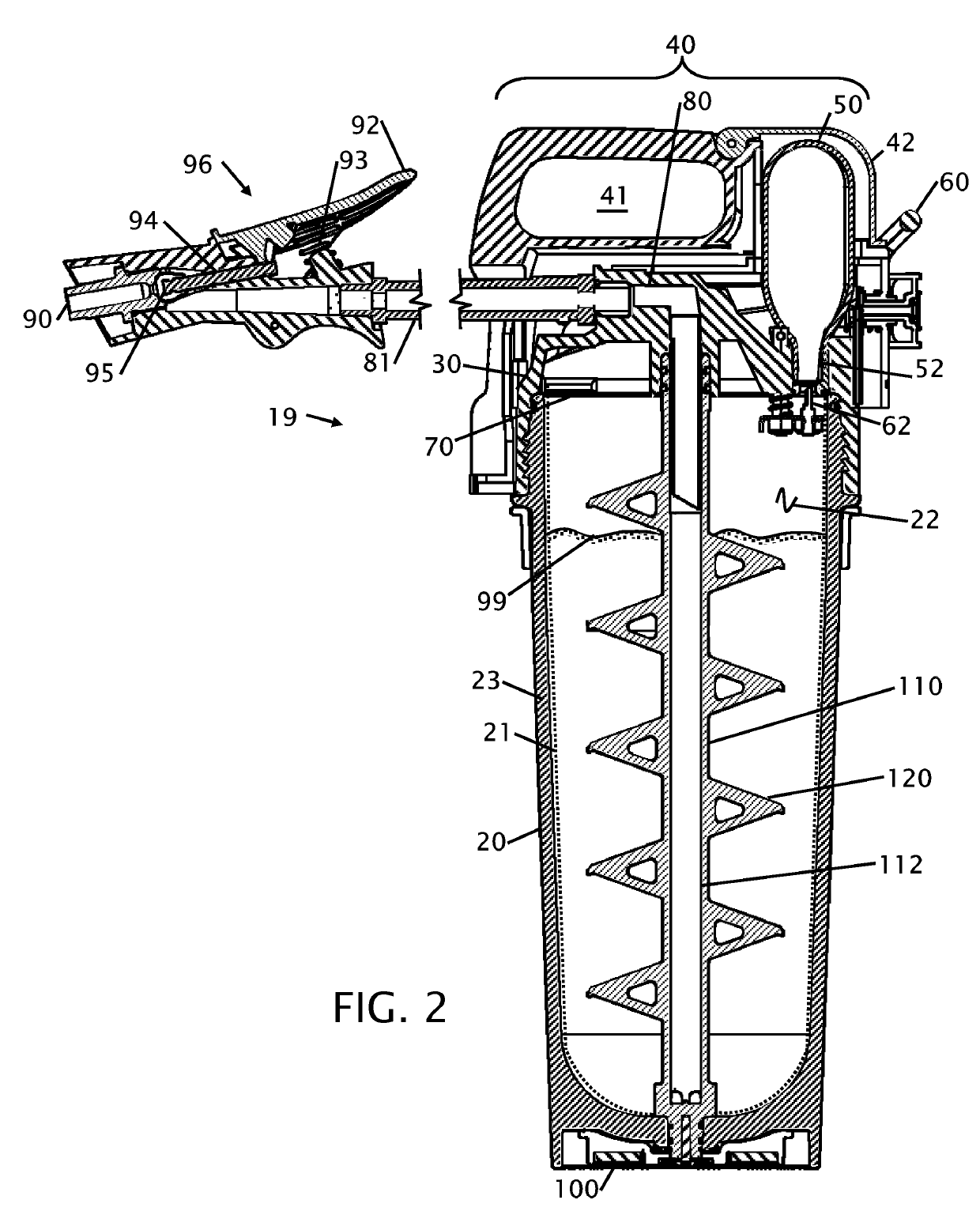
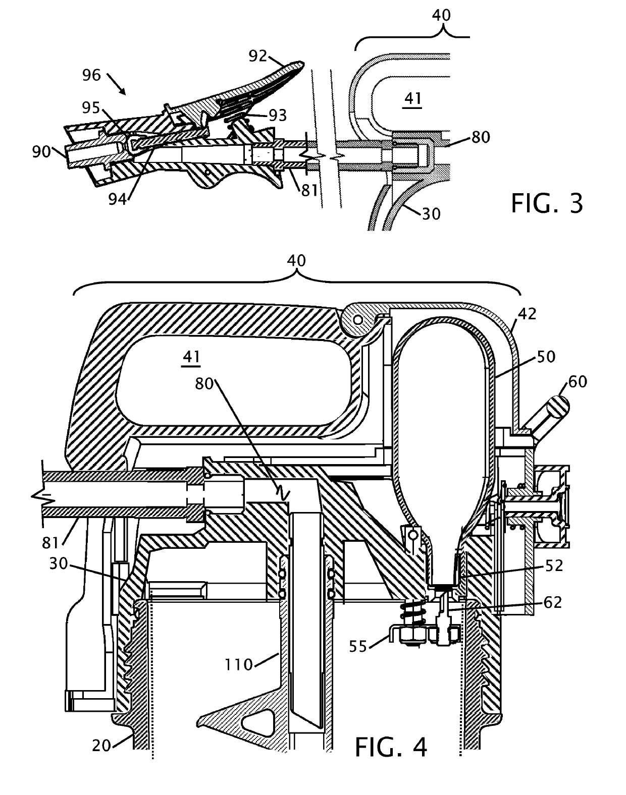
[0032]FIG. 1 shows an exterior perspective view of the fire extinguisher 19. The fire extinguisher 19 is substantially a cylindrical shape with a bottom housing 20 and top housing 30. In the preferred embodiment the bottom housing 20 and top housing 30 is made from a lightweight resilient material such as plastic, but could also be made of other materials, including steel, brass, copper or aluminum. The bottom housing 20 may further be fabricated from a transparent material to allow for visual inspection within the fire extinguisher 19. The top housing 30 is screwed onto the bottom housing 20, but it could also be attached with a bayonet or latching mechanism. The bottom housing 20 has an enlarged opening to allow easier filling of the bottom housing 20 with fire suppressant materials. A wall hanging mechanism can be incorporated into the top housing 30 of the fire extinguisher 19, or could wrap around the body of the bottom housing 20, or could fork the top housing 30 of the fire e...


PUM


Abstract

Improvements to a portable fire extinguisher are disclosed. The improvements allow for frequent and simplified inspection and maintenance of a fire extinguisher with minimal training and without need for custom equipment. The improvements include an anti-bridging mechanism that can be articulated from the exterior of the chamber to fluff, mix or stir the powder within the chamber to keep it in a liquefied state. Additional improvements include a larger opening to more quickly fill and inspect the powder within the chamber. Another improvement includes the use of a CO2 cartridge located external to the chamber to allow easier servicing or replacement of just the CO2 cartridge as well as the ability to maintain the chamber in an un-pressurized condition, allows for non-HASMAT shipping. These features will extend the service intervals while maintaining the fire extinguisher in a ready condition.

Description

CROSS REFERENCE TO RELATED APPLICATIONS[0001]This application is a continuation-in-part of applicant's application 12 / 851,169 filed Aug. 5, 2010, now U.S. Pat. No. 8,757,282 that issued on Jun. 24, 2014, which is a continuation-in-part to application Ser. No. 11 / 578,494 filed on Oct. 12, 2006, now U.S. Pat. No. 7,793,737 that issued on Sep. 14, 2010, and claims priority to International PCT application PCT / US2006 / 041157 that was filed on Oct. 12, 2006, and is a continuation-in-part of application Ser. No. 11 / 515,471 filed on Sep. 1, 2006, now U.S. Pat. No. 7,318,484 that issued on Jan. 15, 2008 and is a continuation-in-part of application Ser. No. 11 / 266,815 filed Oct. 4, 2005, now U.S. Pat. No. 7,128,163 that issued on Oct. 31, 2006, the entire contents of which is hereby expressly incorporated by reference herein.STATEMENT REGARDING FEDERALLY SPONSORED RESEARCH OR DEVELOPMENT[0002]Not ApplicableTHE NAMES OF THE PARTIES TO A JOINT RESEARCH AGREEMENT[0003]Not ApplicableINCORPORATION...

Claims


Application Information

Patent Timeline
Patent Type & Authority Patents(United States)
IPC IPC(8): A62C13/00A62C13/70
CPCA62C13/006A62C13/70
Inventor ROUSSEAU, HECTORROUSSEAU, RANDYBARROWS, RYAN HSEYMOUR, JUSTUN C.
Owner RUSOH INC
Learn More