
Method for producing window elements that can be soldered into a housing in a hermetically sealed manner and free-form window elements produced in accordance with said method

a technology of window elements and housings, applied in the field of methods, can solve the problems of limiting the beam width angle, the limitation of the adaptability to the existing housing, the limitation of the window size, and the related handling expenditure of individual fabrication, so as to reduce the amount of unwanted extraneous radiation, enhance the reliability, and reduce the effect of extraneous radiation

Active Publication Date: 2019-06-25
JENOPTIK OPTICAL SYST +1
View PDF12 Cites 0 Cited by
  • Summary
  • Abstract
  • Description
  • Claims
  • Application Information

AI Technical Summary

Benefits of technology

[0007]Against this background, the invention has the object of finding a better possibility for the production of optical window elements with optical coating which can be soldered into a housing in a hermetically tight manner, which permit a hermetically gastight or vacuum-tight solder connection with the metal housing that is reliable over the long term even under alternating thermal load and which also minimize the penetration of stray radiation and interference radiation into the layer system of the optical coating.

Problems solved by technology

The window elements which are produced result from frame-shaped partial regions which are easy to work with because of their rectangular shape, but are limited with respect to their limiting of the beam width angle in minimized-surface sensors or detectors.
Accordingly, in case of area sensors or image detectors having small dimensions, the window elements produced in this way result in limitations as regards adapting to the existing housing and in loss of quality.
However, a disadvantage consists in the related handling expenditure for individual fabrication and the limitation with respect to window size.
Therefore, individual fabrication of area sensors, image detectors and endoscopes of small dimensions (1-5 mm) is very laborious and a method of this kind is accordingly unsuitable for series production.
In addition, these elements are extremely prone to malfunction and are therefore also cost-intensive.
Further, in the case of glued window elements the permeability (gas permeability) of the glue has a negative impact on the long-term stability of systems on this basis which require a 100-percent hermetically gastight (vacuum-compliance) joint.

Method used


Image

  • Method for producing window elements that can be soldered into a housing in a hermetically sealed manner and free-form window elements produced in accordance with said method
  • Method for producing window elements that can be soldered into a housing in a hermetically sealed manner and free-form window elements produced in accordance with said method
  • Method for producing window elements that can be soldered into a housing in a hermetically sealed manner and free-form window elements produced in accordance with said method

Examples


Embodiment Construction

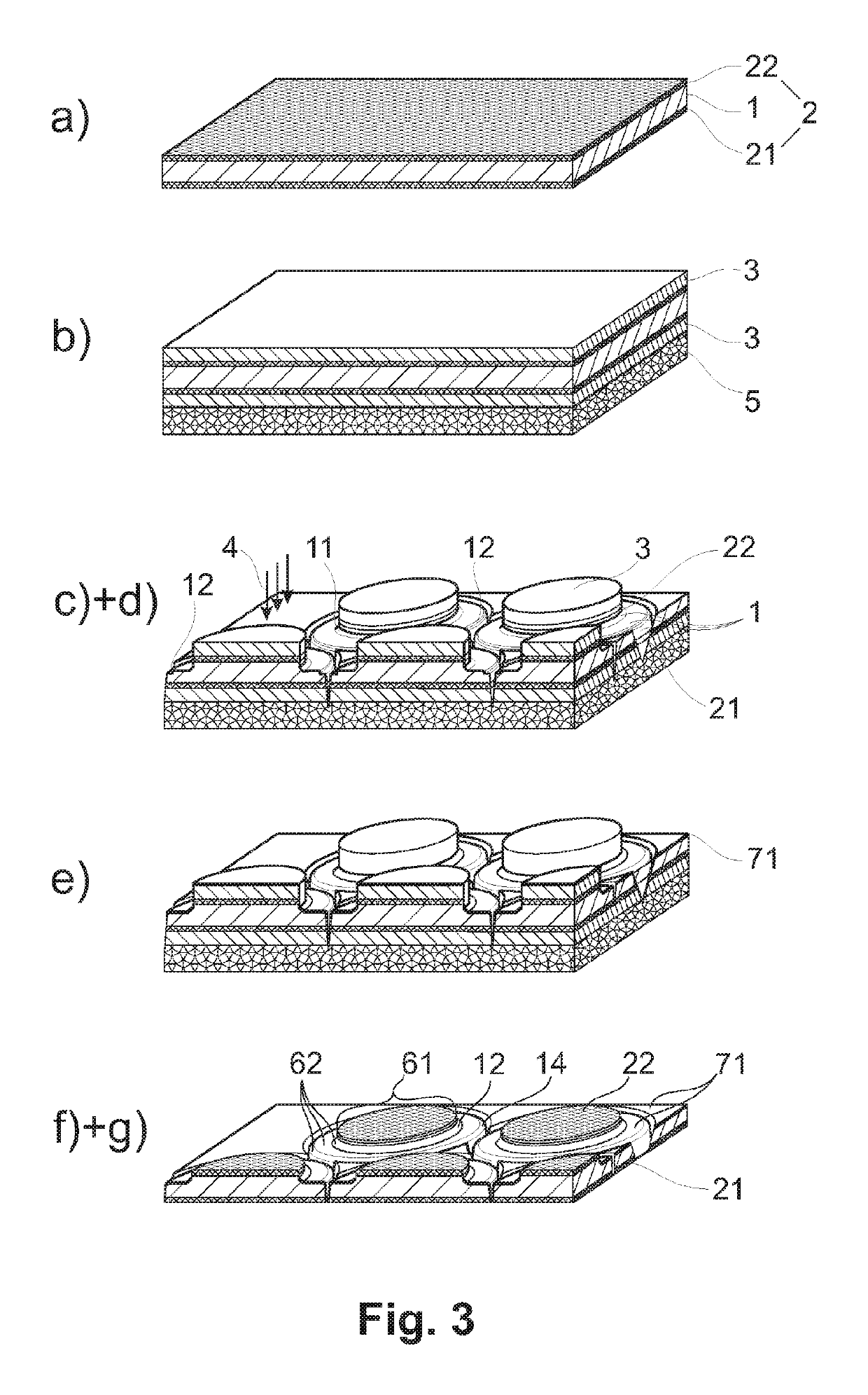
[0045]In a basic variant according to FIG. 1 which is a schematic rendering of the method sequence, the method for the production of window elements 6 which can be soldered into a housing 9 in a hermetically tight manner comprises the following steps:

[0046]a) applying at least one optical coating 2 to at least one surface of an optically transparent, flat substrate material 1,

[0047]b) coating the optical coating 2 with a protective layer 3 which is an etchable layer, meaning a sacrificial layer, for an optical coating 2 which is resistant to etching in this respect,

[0048]c) selectively removing the protective layer 3 and the optical coating 2 from the substrate material 1 in that, for window elements 6 with any geometric shape, at least one required optically active free-form surface 61 is ablated through localized machining by means of a directed machining beam 4 of high-energy radiation in edge regions 62 which circumscribe the periphery of the at least one optically active free-f...


PUM

PropertyMeasurementUnit
radiiaaaaaaaaaa
radiiaaaaaaaaaa
wavelengthaaaaaaaaaa

Abstract

A method for production of window elements which can be soldered into a housing in a hermetically tight manner with optical coating and free-form window elements are disclosed. After application of optical coatings, a protective layer is applied to the optical coating, the two layer systems are selectively removed by means of a machining beam of high-energy radiation for the purpose of ablation of a desired optically active free-form surface for window elements with any geometric shape through a localized machining beam in edge regions of the optically active free-form surface such that the protective layer remains on the optical coating as lift-off mask which is lifted off after applying a metallization for a solder layer by an etching process that acts selectively only on the protective layer but not on the optical coating, and the metallization remains only on the peripheral edge regions circumscribing the free-form surfaces.

Description

RELATED APPLICATIONS[0001]This Application is a Continuation application of International Application PCT / DE2014 / 100165, filed on May 13, 2014, which in turn claims priority to German Patent Applications No. DE 10 2013 008 478.4, filed May 13, 2013, both of which are incorporated herein by reference in their entirety.FIELD OF THE INVENTION[0002]The invention is directed to a method for the production of window elements with optical coating which can be soldered into a housing in a hermetically tight manner and to free-form window elements produced in accordance with the method. Window elements of this type are particularly suitable for closing housings of radiation detectors or radiation sources in a hermetically tight (vacuum-tight) manner while ensuring optical functions, particularly spectral functions.BACKGROUND OF THE INVENTION[0003]A method for the production of window elements which can be soldered in a hermetically tight manner in which stray light or interference radiation ...

Claims


Application Information

Patent Timeline
Patent Type & Authority Patents(United States)
IPC IPC(8): G01J1/02H01L31/0232G02B7/00G02B1/10G02B1/02G01J5/08G01J5/04G02B27/02C09K13/00
CPCG02B27/022G01J1/0271G01J5/045G01J5/0875G02B1/10G02B7/007G02B27/028H01L31/02325G02B1/02C09K13/00
Inventor GITTLER, ELVIRABIERMANN, STEFFENBRODE, WOLFGANGSTOERZNER, FALKO
Owner JENOPTIK OPTICAL SYST
Learn More