
Vital sign monitoring device

a vital sign and monitoring device technology, applied in the field of vital sign monitoring devices, can solve the problems of limiting their usefulness, affecting the usefulness of conventional vital sign monitors, and reducing the usefulness of such devices, so as to facilitate storage and/or stockpiling of such devices, and the effect of convenient us

Inactive Publication Date: 2019-06-25
WACIAN LLC
View PDF4 Cites 1 Cited by
  • Summary
  • Abstract
  • Description
  • Claims
  • Application Information

AI Technical Summary

Benefits of technology

The present patent describes a compact and easily-usable tool for monitoring vital signs of patients. The device can function without stable power sources, making it suitable for situations where power is unavailable or unreliable. It has a small size and can be easily stored and used when needed. The device is efficient and economical to manufacture. It can be used in various situations, such as in developing regions, remote locations, emergency situations, and war zones. The device is designed to promote sanitary use and reduce disease transmission. The attachment mechanism of the electronics package to the patch assembly prevents the reuse of the device after initial attachment. This ensures that the device is properly electrically connected and can function effectively.

Problems solved by technology

The utility of such devices is substantially reduced in areas where mains electricity is unavailable, insufficient, or unreliable, such as in developing nations, in certain emergency situations, in remote locations, and in war zones, for example.
Further, the typically large and clunky construction of such devices limits their usefulness in circumstances where space is a concern.
Additionally, conventional vital sign monitors are relatively costly, making them difficult to obtain and use in many situations where they could otherwise benefit patient care and improve outcomes.

Method used


Image

  • Vital sign monitoring device
  • Vital sign monitoring device
  • Vital sign monitoring device

Examples


Embodiment Construction

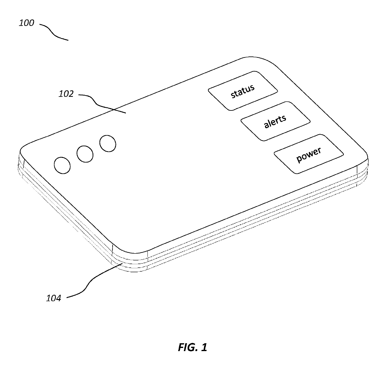
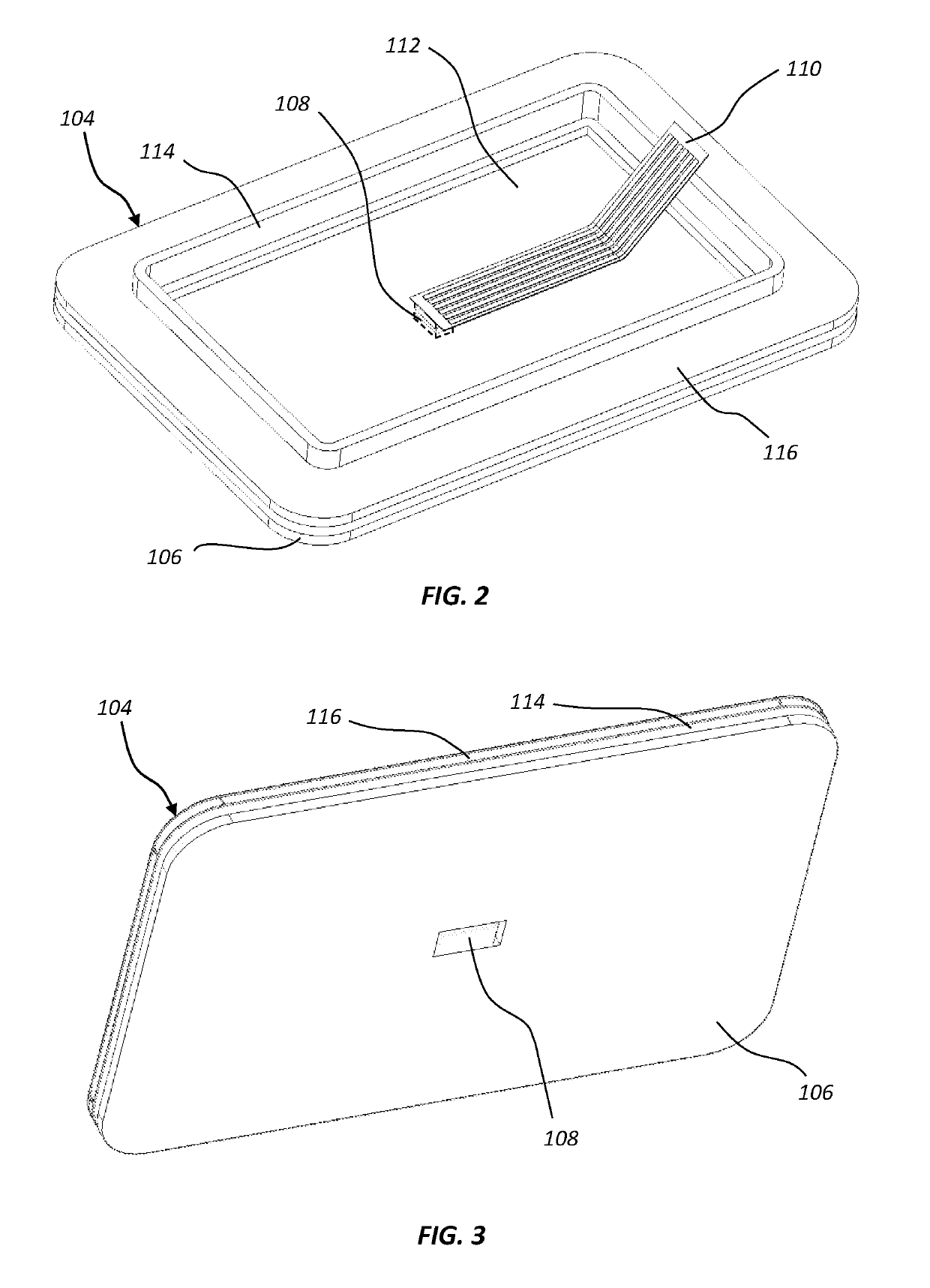
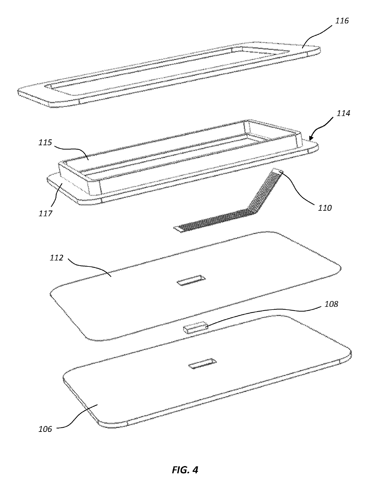
[0020]FIG. 1 illustrates an exemplary vital sign monitoring device 100 which may be positioned on a patient's skin to effectively monitor the patient's vital signs. The illustrated monitoring device 100 includes an electronics package 102 coupled to a patch assembly 104. The patch assembly 104 is configured to contact and adhere to the patient's skin, and the electronics package 102 is configured to couple to the upper side of the patch assembly 104. As explained in more detail below, the patch assembly 104 includes one or more embedded sensors for which are brought into an operative spatial relationship with the patient's skin when the monitoring device 100 is positioned on a patient. The electronics package 102 may function to power the sensor(s), receive readings from the sensor(s), and / or send readings to one or more communicatively coupled computer devices.

[0021]In contrast to conventional vital sign monitoring devices, the illustrated monitoring device 100 is relatively compac...


PUM


Abstract

The present disclosure describes a vital sign monitoring device configured for monitoring one or more patient vital signs. The device includes a disposable patch assembly attachable to a reusable electronics package. The patch assembly includes an adhesive layer for adhering to a patient's skin. A vital sign sensor is embedded within the adhesive layer. A flexible circuit connects to the sensor on an upper side of the adhesive layer, and provides electrical contact between the sensor and the electronics package. The electronics package includes a battery and microcontroller for powering and controlling the sensor.

Description

CROSS-REFERENCE TO RELATED APPLICATIONS[0001]This application claims priority to and the benefit of U.S. Provisional Patent Application Ser. No. 62 / 317,969, filed on Apr. 4, 2016 and titled “VITAL SIGN MONITOR,” the disclosure of which is incorporated herein by this reference in its entirety.BACKGROUND[0002]The monitoring of a patient's vital signs is one of the most fundamental aspects of proper patient care. Vital signs such as body temperature, heart rate, respiration rate, and blood pressure are routinely determined and monitored by health care providers. In a hospital or other emergency care setting, vital sign monitoring is typically done on a continual basis, at least in relatively more developed regions of the world. When one or more vital signs begin to degrade, the speed at which attending health care providers are able to be notified and react can be the difference between life and death of the patient.[0003]Typically, vital sign monitors are constructed as bedside device...

Claims


Application Information

Patent Timeline
Patent Type & Authority Patents(United States)
IPC IPC(8): A61B5/00A61B5/01A61B5/1455
CPCA61B5/6833A61B5/01A61B5/14552A61B2562/227A61B2560/0412A61B2560/0443
Inventor NIEDERAUER, STEFAN JULIUSAHMAD, AZMI ALAAELDINFOGG, BENJAMIN REED
Owner WACIAN LLC
Learn More