
Exhaust heat regenerator for vehicle

a heat accumulator and vehicle technology, applied in the direction of machines/engines, engine starters, lighting and heating apparatus, etc., can solve the problems of small increment in the temperature of coolant, small effect on engine warm-up performance improvement, large energy loss, etc., to achieve rapid heat exchange, enhance heat accumulation performance and heat exchange performance of heat accumulators, and reduce fuel consumption at the initial stage of engine star

Active Publication Date: 2019-06-04
HANON SYST
View PDF23 Cites 4 Cited by
  • Summary
  • Abstract
  • Description
  • Claims
  • Application Information

AI Technical Summary

Benefits of technology

The present invention provides an exhaust heat regenerator for a vehicle that improves heat accumulation and heat exchange performance. This allows for quick engine warming and increased fuel efficiency, reduced pollutant emission, and heating of the passenger compartment after engine start-up. The heat accumulator can absorb and store heat from the coolant for a long period of time, which can then be emitted as needed through the coolant. By doing so, the engine can quickly reach its optimal operating temperature, reducing fuel consumption and achieving improved fuel efficiency. Additionally, the heat accumulator helps to reduce air pollutant emissions during the initial engine start-up period.

Problems solved by technology

However, energy used to drive the vehicle is only portion of the entire generated energy.
In particular, there is a large energy loss due to discharge of high-temperature exhaust gas.
However, in the conventional exhaust heat recovery apparatuses, immediately after an engine starts, that is, when the temperatures of exhaust gas and the exhaust pipe 2 are not increased to a sufficient degree, an increment in the temperature of coolant is small.
Thus, there is little effect on improvement in engine warm-up performance.
Furthermore, the conventional exhaust heat recovery apparatuses are problematic in that it is impossible to heat a passenger compartment immediately after the engine starts in the winter because of the above-mentioned reasons.
Moreover, a heat accumulator which is installed in the conventional exhaust heat recovery apparatuses can neither absorb a large amount of heat nor store it for a long time due to low heat exchange performance and heat accumulation performance.

Method used


Image

  • Exhaust heat regenerator for vehicle
  • Exhaust heat regenerator for vehicle
  • Exhaust heat regenerator for vehicle

Examples


first embodiment

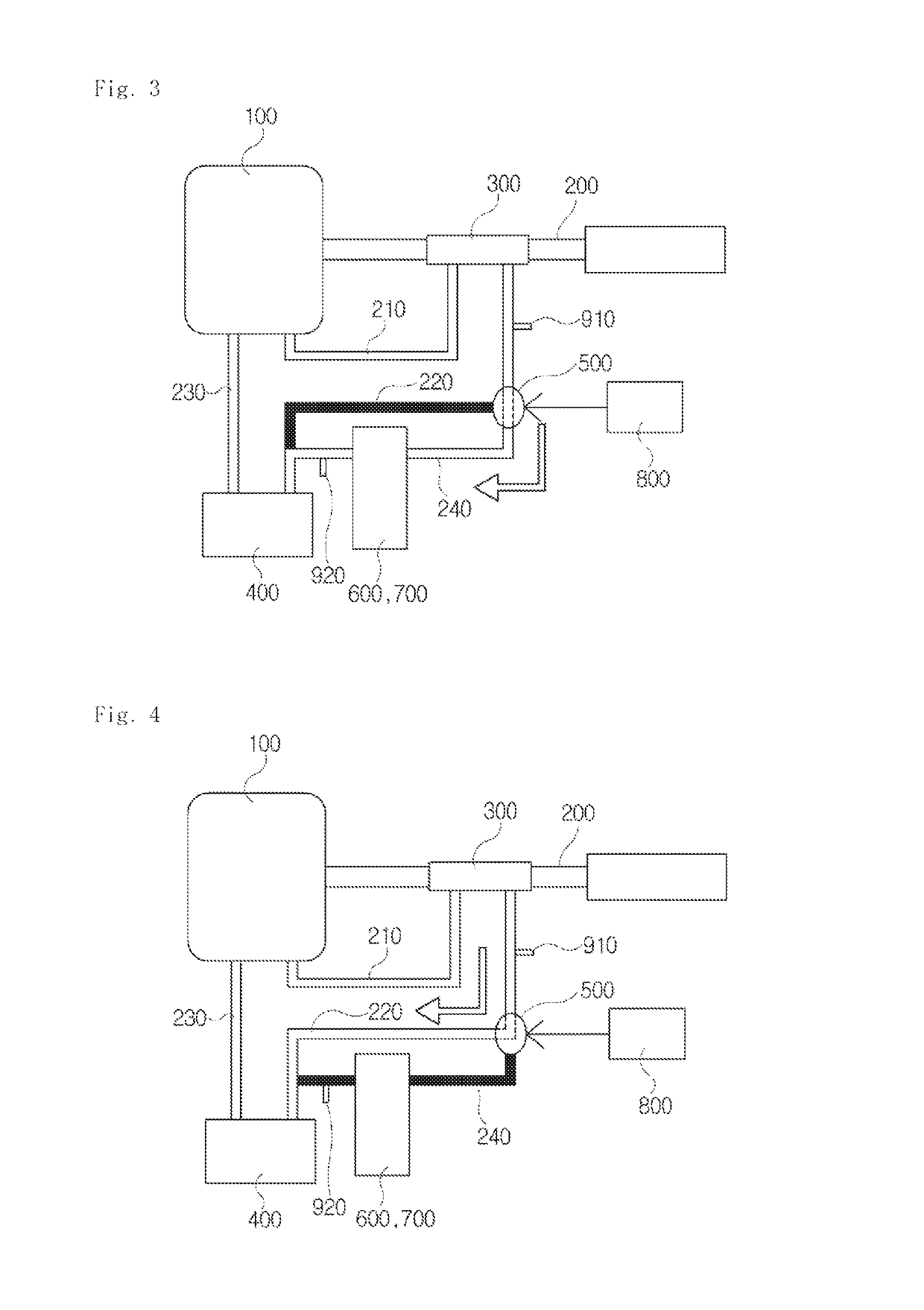
[0091]As shown in FIGS. 6 and 7, the heat accumulator 600 installed in the exhaust heat regenerator for vehicles according to the present invention includes an accumulation heat exchanger 610 through which coolant discharged from the exhaust-heat-recovery heat exchanger 300 passes, an inner casing 620 which encloses the accumulation heat exchanger 610 with a space between it and the heat exchanger 610, and an outer casing 630 which encloses the inner casing 620 with a space between it and the inner casing 620.

[0092]The heat exchanger 610 includes an inlet port 611 and an outlet port 612 on both sides of an upper surface thereof. The inlet port 611 and the outlet port 612 are respectively coupled to both ends of the heat accumulator 600 of the coolant bypass pipe 240, thus forming a coolant path which passes through the accumulation heat exchanger 610.

[0093]A heat storage material injection port 621 is formed on a central portion of an upper surface of the inner casing 620.

[0094]The ...

second embodiment

[0105]FIG. 8 is an exploded perspective view illustrating the configuration of a heat accumulator installed in the exhaust heat regenerator for vehicles according to the present invention. As shown in the drawing, the heat accumulator 700 of the exhaust heat regenerator for vehicles according to the present embodiment includes a heat exchanger 710 through which coolant passes, an inner casing 720 in which the heat exchanger 710 is housed, a heat storage material which is charged into space between the heat exchanger 710 and the inner casing 720, an outer casing 740 which houses the inner casing 720, and an insulation space which is formed between the inner casing 720 and the outer casing 740.

[0106]As shown in FIG. 9, the heat exchanger 710 is configured by stacking a plurality of planar tubes 711. The heat exchanger 710 is manufactured in a cylindrical shape so as to minimize a heat exchange area between it and the outside in an insulated state. Therefore, each of the planar tubes 7...


PUM


Abstract

Disclosed herein is an exhaust heat recovery apparatus for a vehicle, in which a heat accumulator has improved heat accumulation performance and heat exchange performance, whereby an engine can be rapidly warmed up in a cold start so that fuel efficiency can be enhanced, a pollutant emission rate can be reduced, and it is possible to heat a passenger compartment immediately after the engine starts.

Description

[0001]This application is a § 371 of International Application No. PCT / KR2015 / 006032 filed on Jun. 15, 2015, and claims priority from Korean Patent Application Nos. 10-2014-0091203 filed on Jul. 18, 2014 and 10-2014-0135284 filed on Oct. 7, 2014.BACKGROUND OF THE INVENTION[0002]Field of the Invention[0003]Exemplary embodiments of the present invention relate to an exhaust heat regenerator for a vehicle, and more particularly, an exhaust heat regenerator for a vehicle which is able to collect exhaust heat using coolant, store in a heat accumulator, and use the exhaust heat stored in the heat accumulator, during a cold start operation or for heating a passenger compartment.[0004]Description of the Related Art[0005]Engines for vehicles are a power generation apparatus for a vehicle which converts thermal energy generated by burning fuel into kinetic energy and transmits the kinetic energy to wheels through a drive line, thus enabling the vehicle to drive.[0006]However, energy used to d...

Claims


Application Information

Patent Timeline
Patent Type & Authority Patents(United States)
IPC IPC(8): F02N19/10F01N5/02F01N13/08F01P3/20F01P7/16F28D20/00F01N13/14B60H1/02B60H1/00B60H1/20
CPCF02N19/10B60H1/00492B60H1/025B60H1/20F01N5/02F01N13/14F01P3/20F01P7/16F28D20/00F01N13/08F01N2240/10Y02E60/14
Inventor GU, JUNG SAMSHIN, HYUN KUNOH, KWANG HUNJEON, YOUNG HA
Owner HANON SYST
Learn More