
Alignment sleeve assembly and fiber optic adapter

a technology of alignment sleeves and adapters, which is applied in the direction of optics, instruments, optical light guides, etc., can solve the problems of increasing the uncertainty of connection loss, increasing the connection loss, and machining errors of the alignment sleeves, so as to improve the alignment accuracy of the coupled connectors

Active Publication Date: 2019-05-28
COMMSCOPE TELECOMM (SHANGHAI) CO LTD
View PDF407 Cites 13 Cited by
  • Summary
  • Abstract
  • Description
  • Claims
  • Application Information

AI Technical Summary

Benefits of technology

[0010]According to an object of the present invention, there is provided an alignment sleeve assembly and a fiber optic adapter comprising the alignment sleeve assembly, in which an alignment sleeve may be adjusted to and fixed at a predetermined circumferential angle, at which the fiber optic insertion loss is minimal, with respect to a mating retainer. In this way, it improves the alignment accuracy of a pair of coupled fiber optic connectors.
[0012]According to an exemplary embodiment of the present invention, when the alignment sleeve is held at the predetermined circumferential angle relative to the mating retainer, an alignment error between fiber cores of fibers, inserted into the alignment sleeve of the fiber optic adapter, of a pair of fiber optic connectors is minimal.
[0025]According to another exemplary embodiment of the present invention, the fiber optic adapter further comprises a fixation element adapted to be mounted on the housing and hold a tube-like body of the mating retainer, so as to prevent the mating retainer from being pulled out of the housing.
[0039]In the above various exemplary embodiments of the present invention, the adjustment element is constructed to adjust the circumferential angle of the alignment sleeve with respect to the mating retainer to the predetermined circumferential angle, for example, at which the fiber insertion loss of the coupled connectors is minimal, and hold the alignment sleeve at the predetermined circumferential angle. In this way, it may improve the alignment accuracy of the coupled connectors.

Problems solved by technology

In the prior art, there is machining error in the alignment sleeve, for example, inner wall roundness of the alignment sleeve is not enough, and wall thickness of the alignment sleeve is not uniform.
As a result, when ferrules of a pair of fiber optic connectors are inserted into the alignment sleeve of the fiber optic adapter from opposite ends of the alignment sleeve and coupled with each other, in addition to an alignment error, which will lead to a connection loss, between fiber cores of the coupled connectors, the alignment sleeve will also cause a certain alignment error, it will further increase the connection loss or increase the connection loss uncertainty.
Therefore, minimizing the connection loss by positioned the alignment sleeve at the particular circumferential angle is not recognized and well utilized yet by the existing design.
Thereby, the insertion loss of the entire optical fiber interconnection system is not always kept in a state of minimum loss.
In other words, the random nature of the circumferential angle of the alignment sleeve affects the total insertion loss of the fiber interconnection system.
Such situation does not meet strict requirements on ultra low insertion loss of optical fiber interconnection system in future and requirements on the repeatability of the ultra low insertion loss after the fiber optic connectors are decoupled.

Method used


Image

  • Alignment sleeve assembly and fiber optic adapter
  • Alignment sleeve assembly and fiber optic adapter
  • Alignment sleeve assembly and fiber optic adapter

Examples


first embodiment

[0059]FIGS. 1-13 show a fiber optic adapter according to a first exemplary embodiment of the present invention.

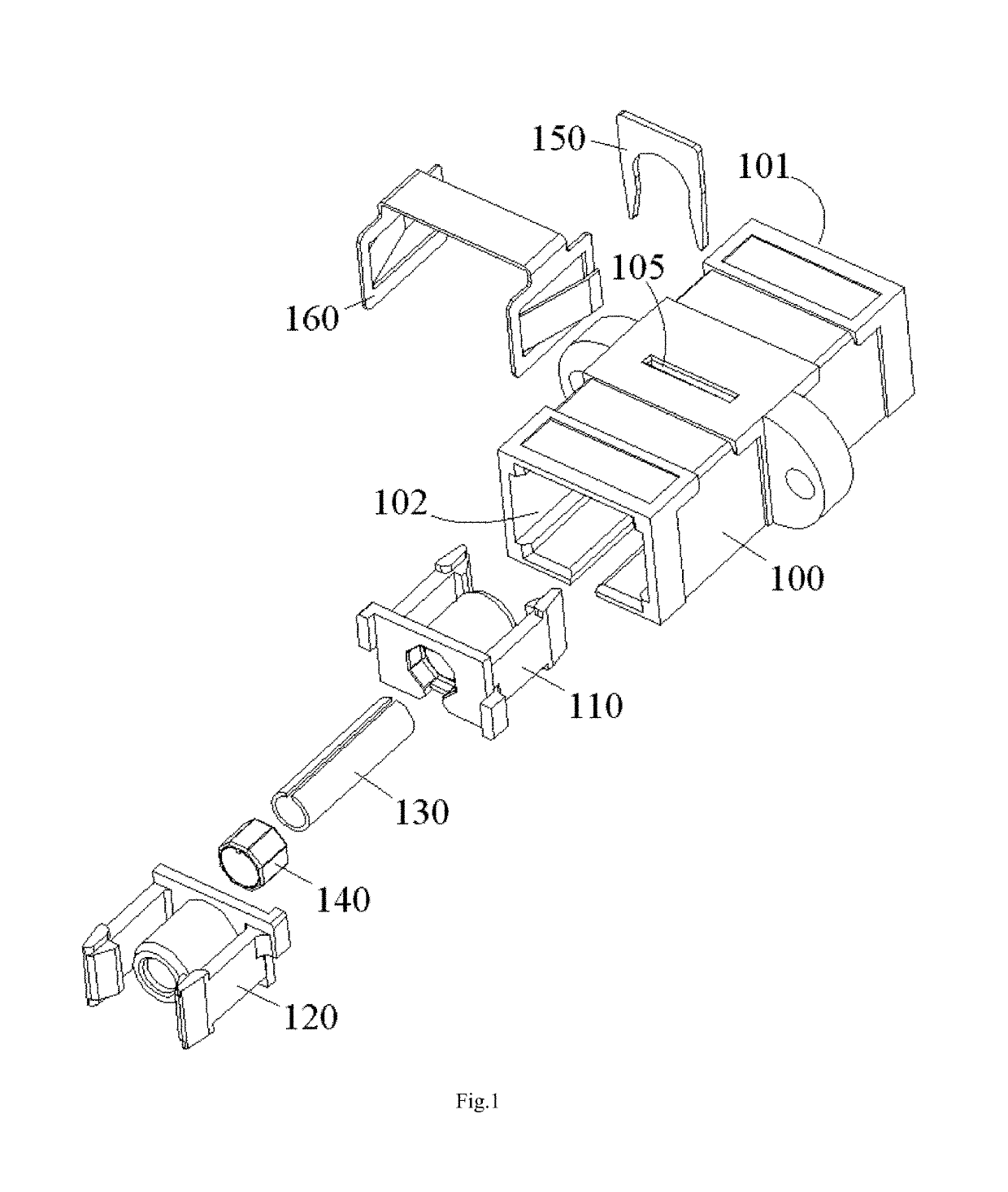
[0060]FIG. 1 is an illustrative exploded view of the fiber optic adapter according to a first exemplary embodiment of the present invention.

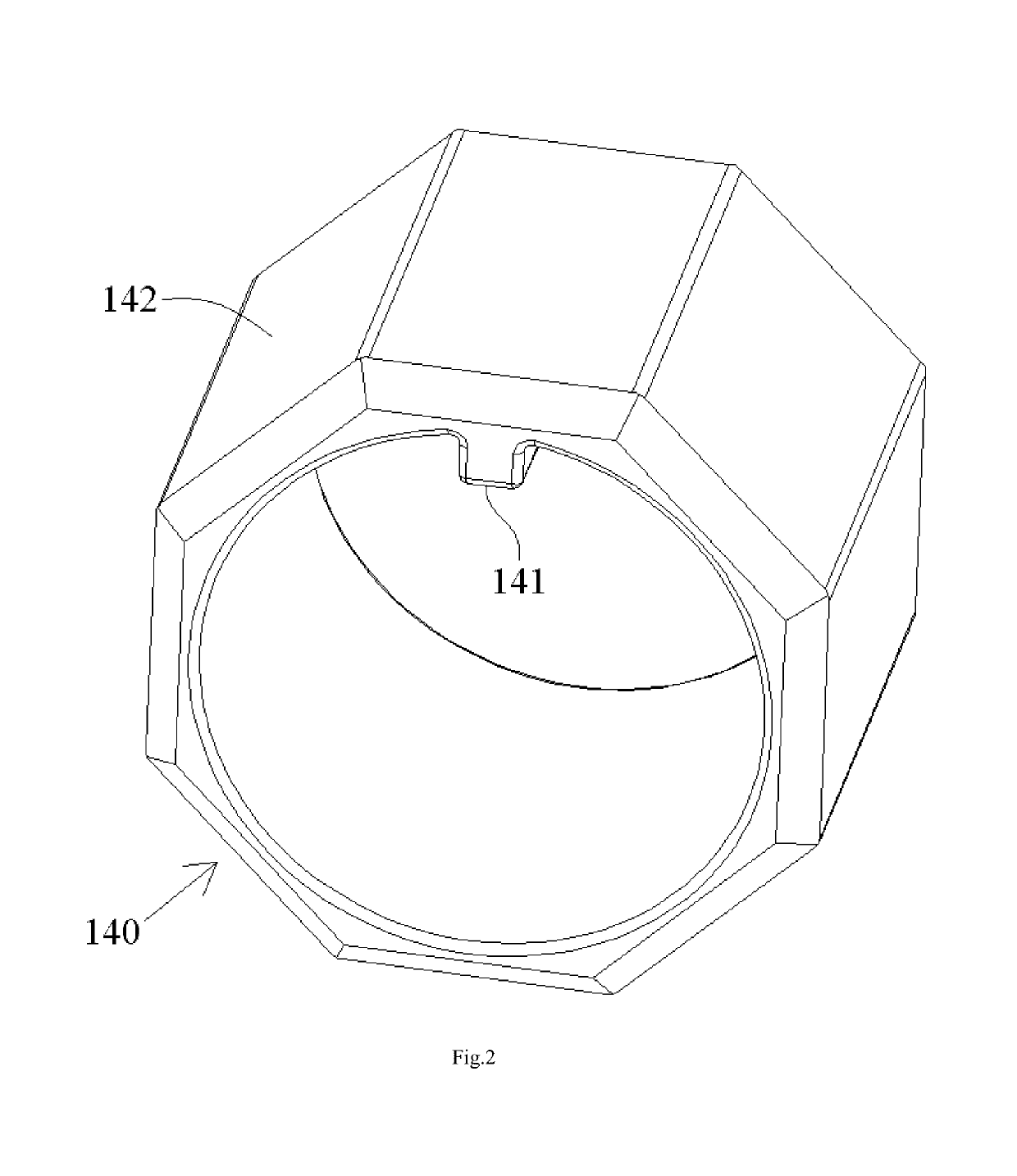
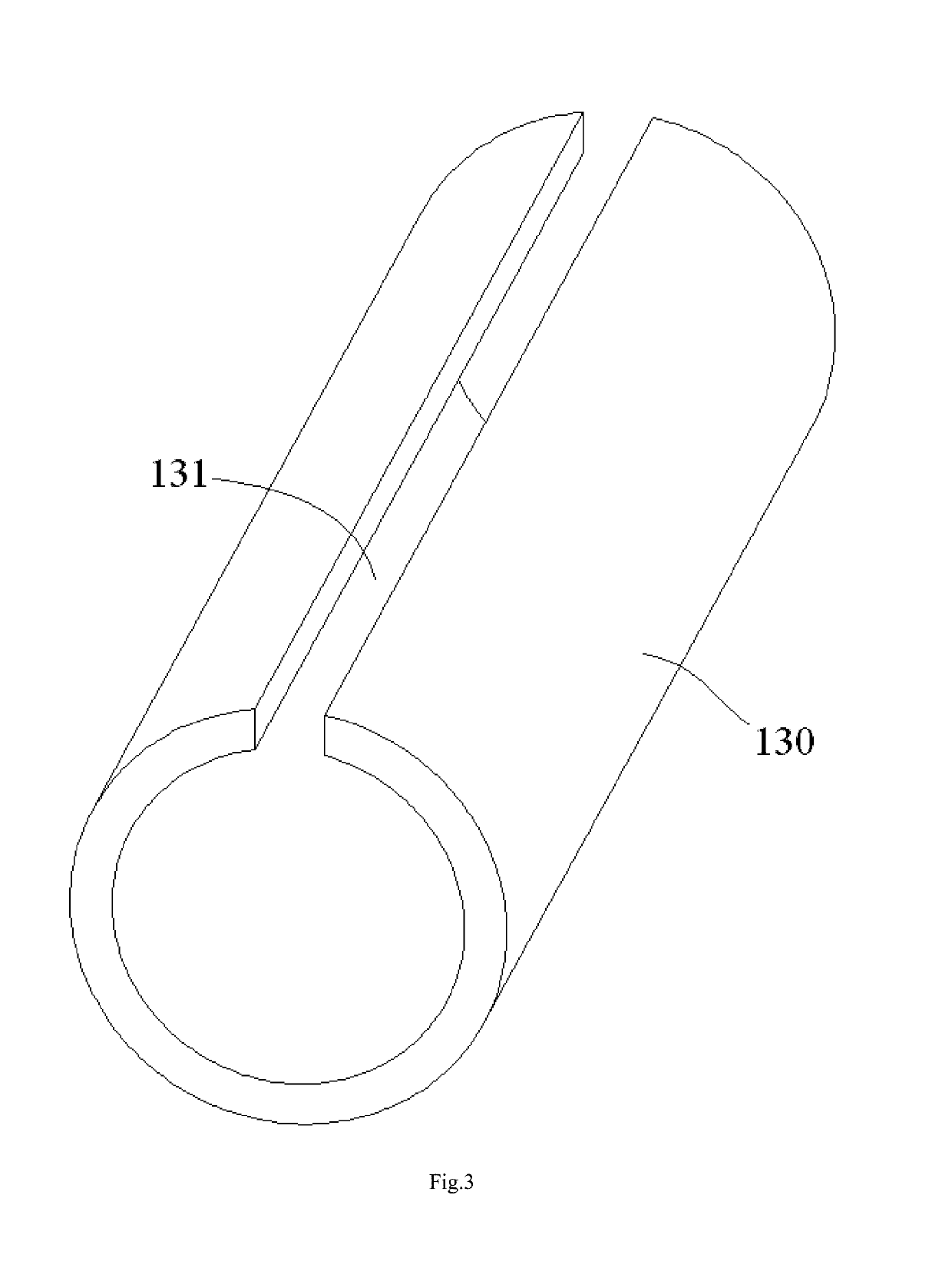
[0061]As shown in FIG. 1, it shows a LC type of fiber optic adapter. The fiber optic adapter mainly comprises a housing 100, a mating retainer 110, 120, an alignment sleeve 130 and an adjustment element 140.

[0062]As shown in FIG. 1, the mating retainer 110, 120 comprises a first mating retainer 110 and a second mating retainer 120 capable of being assembled together. The mating retainer 110, 120 is configured to receive the alignment sleeve 130 therein and lock coupled fiber optic connectors (not shown) in place. A ferrule of one of the fiber optic connector is adapted to be inserted into the alignment sleeve 130 through an insertion port 101, 102 of the fiber optic adapter. In this way, fiber cores of the fiber optic connectors are cou...

second embodiment

[0088]FIGS. 14-16 show a fiber optic adapter according to a second exemplary embodiment of the present invention.

[0089]FIG. 14 is an illustrative perspective view of a fiber optic adapter according to a second exemplary embodiment of the present invention, wherein an alignment sleeve assembly is mounted to a first mating retainer 210; FIG. 15 is an illustrative view of assembling the first mating retainer 210 of FIG. 14 to a second mating retainer 220; and FIG. 16 is an illustrative perspective view of an assembled fiber optic adapter according to a second exemplary embodiment of the present invention.

[0090]As shown in FIGS. 14-16, in the second embodiment, the fiber optic adapter is adapted to couple a plurality of pairs of fiber optic connectors at the same time. A plurality of alignment sleeves 230, configured to align ferrules of the pairs of fiber optic connectors, are received in the mating retainer 210, 220.

[0091]Also, in the second embodiment shown in FIGS. 14-16, the fiber ...


PUM


Abstract

A fiber optic adapter, including: a mating retainer; an alignment sleeve received in the mating retainer, a ferrule of a fiber optic connector being adapted to be inserted into the alignment sleeve through an insertion port of the fiber optic adapter; and an adjustment element configured to adjust a circumferential angle of the alignment sleeve relative to the mating retainer to a predetermined circumferential angle and hold the alignment sleeve at the predetermined circumferential angle relative to the mating retainer. The adjustment element may adjust the circumferential angle of the alignment sleeve with respect to the mating retainer to the predetermined circumferential angle, for example, at which the fiber insertion loss of the coupled connectors is minimal, and hold the alignment sleeve at the predetermined circumferential angle. In this way, it may improve the alignment accuracy of the coupled connectors.

Description

[0001]This application is a National Stage Application of PCT / CN2016 / 082021, filed on 13 May 2016, which claims benefit of Serial No. 201510247621.4, filed on 15 May 2015 in China and Serial No. 201520319609.5, filed on 15 May 2015 in China and which applications are incorporated herein by reference. To the extent appropriate, a claim of priority is made to each of the above disclosed applications.BACKGROUND OF THE INVENTION[0002]Field of the Invention[0003]The present invention relates to an alignment sleeve assembly and a fiber optic adapter comprising the alignment sleeve assembly.[0004]Description of the Related Art[0005]In the prior art, a fiber optic adapter (for convenience of description, herein take a single-fiber SC adapter as an example) generally comprises an alignment sleeve, a mating retainer for receiving the alignment sleeve therein and locking a pair of coupled fiber optic connectors, a housing, a buckle type fixing clamp spring and a warranty buckle (optional).[000...

Claims


Application Information

Patent Timeline
Patent Type & Authority Patents(United States)
IPC IPC(8): G02B6/38
CPCG02B6/3871G02B6/3874G02B6/3825G02B6/38G02B6/3877
Inventor TONG, ZHAOYANGCHENG, XINGJUNLIU, LEI
Owner COMMSCOPE TELECOMM (SHANGHAI) CO LTD
Learn More