
High power microwave weapon system

a microwave and weapon technology, applied in the direction of antennas, basic electric elements, electric devices, etc., can solve the problems of large system technological uncertainties, huge cost, and inability to meet the needs of military personnel,

Active Publication Date: 2019-05-21
PODGORSKI ANDREW STAN
View PDF4 Cites 2 Cited by
  • Summary
  • Abstract
  • Description
  • Claims
  • Application Information

AI Technical Summary

Benefits of technology

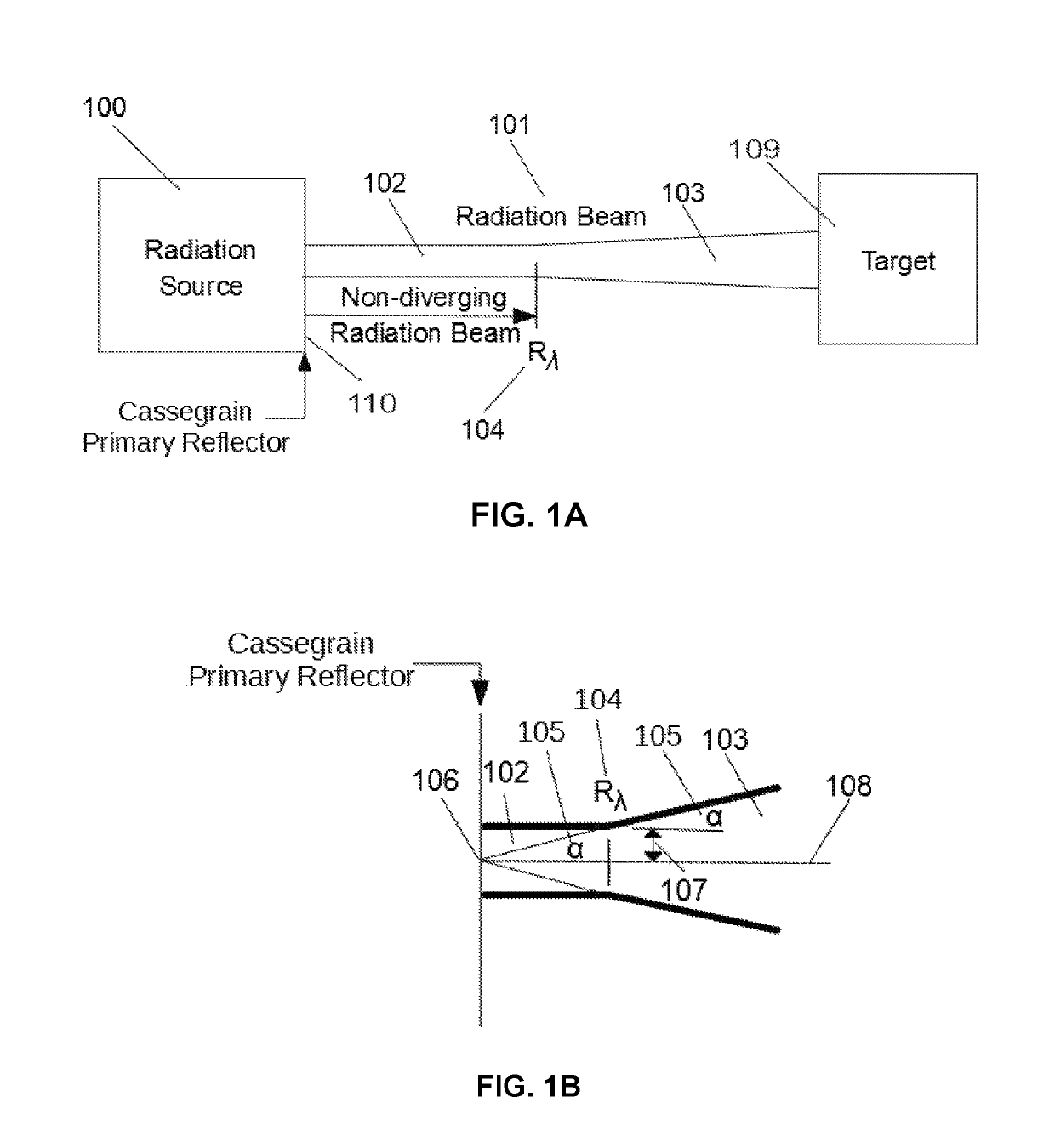
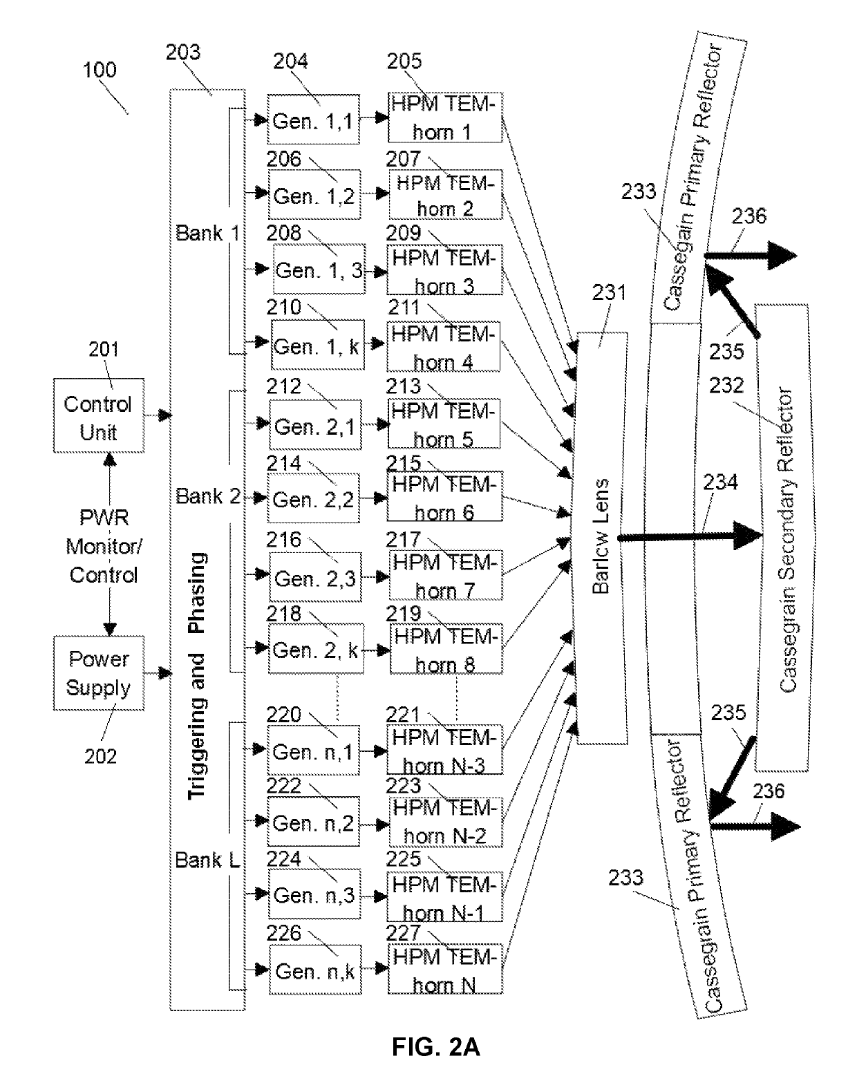
The invention is a new way to generate high power microwaves using a Cassegrain antenna, which allows for more efficient use of the microwaves. The ultrahigh power pulses create less ionization potential, which means there is less energy needed to create an ion. This allows for increased power and a smaller antenna. The invention also explains a new property of the Cassegrain antenna that allows for smooth pulse amplitude and optimal dimensioning of the microwave components. The invention also matches the spectral components of the generated signals to the strongest electromagnetic coupling, ensuring the most efficient field-induced effects and achieving field levels that were previously unobsolete. Overall, the invention allows for improved performance of the Cassegrain antenna in the generation of ultrahigh power microwaves.

Problems solved by technology

Critics pointed to the vast technological uncertainties of the system, in addition to its enormous cost.
Although work was begun on the program, the technology proved to be too complex and much of the research was cancelled by later administrations.
Typical high power microwave (HPM) weapons are ineffective and unreliable, having electric fields less than 100 kV / m (105 Volts / meter) and GW (109 Watts) power pulses significantly longer than 1 nanosecond (10−9 seconds).
This has led to huge impractical HPM weapon designs too costly to build, too heavy to ship, too large to fit, and too inefficient to power.
It is clear that merely scaling up the radiation time interval or physical sizes is not the answer to increasing the probability of target damage.
As such, the off-the-band high frequencies electromagnetic interactions does only “burn” the target without engaging the plasma molecular frequencies, making the excitation process energy inefficient.
Simply the wedges needed previously to separate the vertical and horizontal illumination as well as dielectric lenses, low surface breakdown voltage and low dielectric breakdown voltage did not allow increasing the E-field at least 10 times as needed.

Method used


Image

  • High power microwave weapon system
  • High power microwave weapon system
  • High power microwave weapon system

Examples


Embodiment Construction

[0052]Example embodiments of the invention now will be described more fully hereinafter with reference to the accompanying and incorporated by reference (cross-referenced) drawings, in which embodiments of the invention are shown. This invention may, however, be embodied in many different step sequences, forms, structures, or materials and should not be construed as limited to the embodiments set forth herein. Rather, these embodiments are provided so that this disclosure will be thorough and complete, and will fully convey the scope of the invention to those skilled in the art.

[0053]Like identified numbers refer to like elements throughout. The use of asterisks herein is indicative of multiplication operations unless otherwise noted.

[0054]It should be noted that, as used in the specification and the appended claims, the singular forms “a” and “the” include plural referents, unless the context clearly dictates otherwise. Thus, for example, reference to an array can include reference...


PUM


Abstract

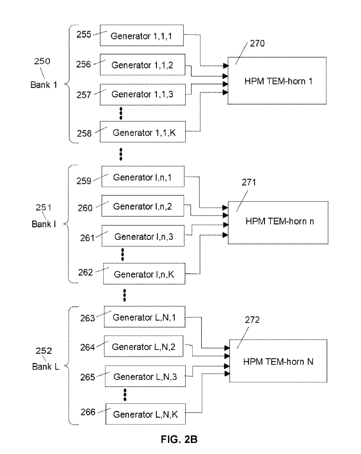
This invention allows combining broadband GW(10+9 Watt), peak power to achieve MV / m(10+6 Volt / meter), and GV / m(10+9 Volt / meter), radiated E-fields, in the range of air or vacuum breakdown in the entire electromagnetic spectrum, including optical frequencies and beyond. Use of many antennas and independently triggered generators allows achieving GV / m field, while by preventing the E-field induced breakdown it provides control of peak power and energy content at targets. The achieved broadband MV / m E-field levels and energy density significantly exceed levels required for destruction of distant electronic targets; therefore this invention radically improves the effectiveness of the electromagnetic weapons. Furthermore, collimating multiplicity of MV / m beams allows reaching GV / m E-field that exceeds by orders of magnitude the air or vacuum breakdown needed for broadband plasma excitation at resonance plasma frequencies in the 300 GHz range.

Description

CROSS REFERENCE TO RELATED APPLICATIONS[0001]The present application is a continuation-in-part of co-pending U.S. application Ser. No. 14 / 161,561, filed Jan. 22, 2014. The disclosure of this application is incorporated by reference herein in its entirety.TECHNICAL FIELD[0002]This invention generally relates to directed high power electromagnetic weaponry used to damage, disable, or render inoperable by transmitting electromagnetic radiation from a safe but effective distance which thereinafter is coupled into a wide range of target types. Although examples herein comprise on-the-axis Cassegrain antenna configurations and applications, this submission applies to off-the-axis Cassegrain antennas as well.BACKGROUND OF THE INVENTION[0003]Advanced non-conventional weaponry has been of increasing importance since Ronald Reagan called for an anti-missile defense system in 1983 and dubbed; “star wars.” Among the potential components of the defense system were both space- and earth-based las...

Claims


Application Information

Patent Timeline
Patent Type & Authority Patents(United States)
IPC IPC(8): F41H13/00H01Q19/06H01Q19/17H01Q19/19H01Q13/02
CPCF41H13/0068H01Q13/02H01Q19/19H01Q19/17H01Q19/062
Inventor PODGORSKI, ANDREW STAN
Owner PODGORSKI ANDREW STAN
Learn More