
Highly retractable intravascular stent conveying system

a conveying system and high-retractable technology, applied in the field of minimal invasive surgery medical equipment, can solve the problems of difficult manufacturing of rotation driving assembly, inability to accurately locate the self-expandable stent by using such delivery systems, and inability to meet the requirements of surgery

Active Publication Date: 2019-05-21
SUZHOU INNOMED MEDICAL DEVICE
View PDF22 Cites 3 Cited by
  • Summary
  • Abstract
  • Description
  • Claims
  • Application Information

AI Technical Summary

Benefits of technology

The invention is a delivery system for intravascular stents that prevents the stents from moving during placement, which can improve their accuracy and effectiveness. The system has a balanced structure that is easy to manufacture and without interference during operations. The use of a triple-layer tube structure and a driving member to move the stent in opposite directions can effectively offset the axial retraction of the stent.

Problems solved by technology

However most of the self-expandable stents cannot be accurately located by using such delivery systems due to high retractability and highly axial retractability of the stents.
Therefore, such a delivery system doesn't meet the requirements for surgery.
However, it is difficult to manufacture a rotation driving assembly in such delivery system, and if such delivery system is used to position a stent with long axial length, it needs a hand shank with increased length.
It is inconvenient for the doctors to operate such delivery system.

Method used


Image

  • Highly retractable intravascular stent conveying system
  • Highly retractable intravascular stent conveying system
  • Highly retractable intravascular stent conveying system

Examples


Embodiment Construction

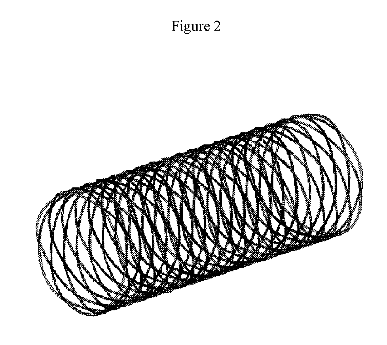
[0032]Described herein is a delivery system for intravascular stents with axial high retractability. As shown in FIG. 2, the intravascular stent with axial high retractability is formed by winding nickel-titanium alloy wires, including a cylindric main body and round corner portions disposed on the both ends of the main body. The main body is formed by forward and backward crossing and overlapping the nickel-titanium alloy wires. The main body is formed by a set of diamond grid units. There is no fixed limitation on the node overlapping on the diamond grid units of such intravascular stent. Such a node which lacks fixed limitation allows the nickel-titanium alloy wires to rotate and twist, rather than exhibit a circle movement. Therefore, such a configuration can avoid bending stress which is high, typically occurs around the node in a laser cutting stent. This mechanism can be shared by the same grid stent, but a new stent with closed-end circles and low corners, which is made from...


PUM


Abstract

A highly retractable intravascular stent delivery system, including a tube assembly and a rotation driving assembly. The tube assembly includes an outer tube 5, an intermediate tube 6, and inner tube 7, wherein an intravascular stent 3 and a stent retaining block 4 are provided within the outer tube 5. The rotation driving assembly includes a housing 9, an outer screw 19, and an intermediate screw 14 located within the housing 9, as well as a driving member. The driving member allows two screws to rotate at opposite directions, so as to drive the outer tube 5 to move toward the proximal end, and the intermediate tube 6 pushes the stent retaining block 4 and the intravascular stent 3 to move toward the distal end. The system uses three-lay tube structure and uses driving gear to drive two screws to move at directions opposite to each other, such that the intermediate tube 6 and the outer tube 5 are driven to move to directions opposite to each other. Therefore, the axial retraction of the intravascular stents can be effectively offset and axial movement of the intravascular stents due to axial retraction of the intravascular stents is avoided, thereby accurately implanting the stents into the body.

Description

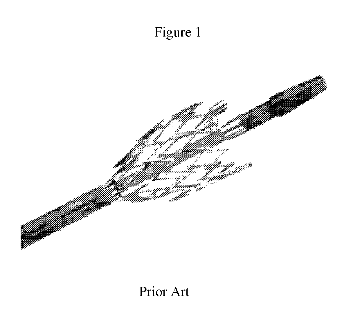
FIELD OF THE INVENTION[0001]Generally, the present invention relates to the field of medical apparatus for minimal invasive surgery. In particular, the present invention relates to a delivery system for intravascular stents.BACKGROUND OF THE INVENTION[0002]Minimal invasive surgeries which utilize stents have a certain advantages such as small wound size, reduced complications, and satisfying prognosis, in comparison with traditional peripheral artery surgeries. Currently, minimal invasive surgeries become major methods for treating peripheral artery stenosis.[0003]As shown in FIG. 1, a delivery system is needed to implant intravascular stents into a body. A delivery system being currently used is shown in Chinese Patent Application CN201110190183.4, which includes a hollow inner tube and an outer tube connected to each other. Guide wires used during surgery pass through the hollow portion in the inner tube and intravascular stents are disposed between the inner tube and the outer tu...

Claims


Application Information

Patent Timeline
Patent Type & Authority Patents(United States)
IPC IPC(8): A61F2/95A61M25/01A61F2/962A61M25/00A61F2/966
CPCA61F2/95A61F2/962A61F2/966A61M25/0102A61M25/00A61F2002/9665A61F2002/9517A61F2/9517
Inventor GONG, XIAOYAN SHAWNZHOU, XIANGXUE, GUANHUAZHOU, WEIKUNQIU, PENGCHONG
Owner SUZHOU INNOMED MEDICAL DEVICE
Learn More