Soundproof structure body

Pending Publication Date: 2021-07-29
FUJIFILM CORP
View PDF0 Cites 0 Cited by
  • Summary
  • Abstract
  • Description
  • Claims
  • Application Information

AI Technical Summary

Benefits of technology

The present invention aims to provide a soundproof structure that can effectively prevent reflected waves and opening end reflections from affecting the structure. This is achieved by appropriately positioning the resonance type soundproof structure and the opening end portion of ducts, pipelines, or other structures. The invention also allows for a smaller size and high absorption with a smaller number of resonance type soundproof structures. Overall, the technical effects of the invention allow for improved soundproofing and reduced size of the soundproof structure.

Problems solved by technology

Therefore, there is a problem that a device configuration is large and the sound cannot be absorbed compactly.
In addition, since the silencer disclosed in JP1985-008232Y (JP-S60-008232Y) uses a sound absorbing material to absorb the sound, there is a problem that peak sound cannot be efficiently absorbed in a case where the noise source emits the peak sound.
In the silencer described in JP2944552B, since it is necessary to place an upstream resonator in a place where a sound pressure is high due to an interference between a reflected wave and an incident wave from a downstream resonator, and each of the two upstream and downstream resonators needs to have eight resonant openings in the circumferential direction, there is a problem that this method is not suitable, for example, in a case where there are spatial restrictions.
In addition, in the silencer disclosed in JP2944552B, since at least two resonators are required to obtain high absorption, and at least about a quarter of the wavelength of target sound is essential, there is a problem that it is not suitable for miniaturization.

Method used


Image

  • Soundproof structure body
  • Soundproof structure body
  • Soundproof structure body

Examples


example 1

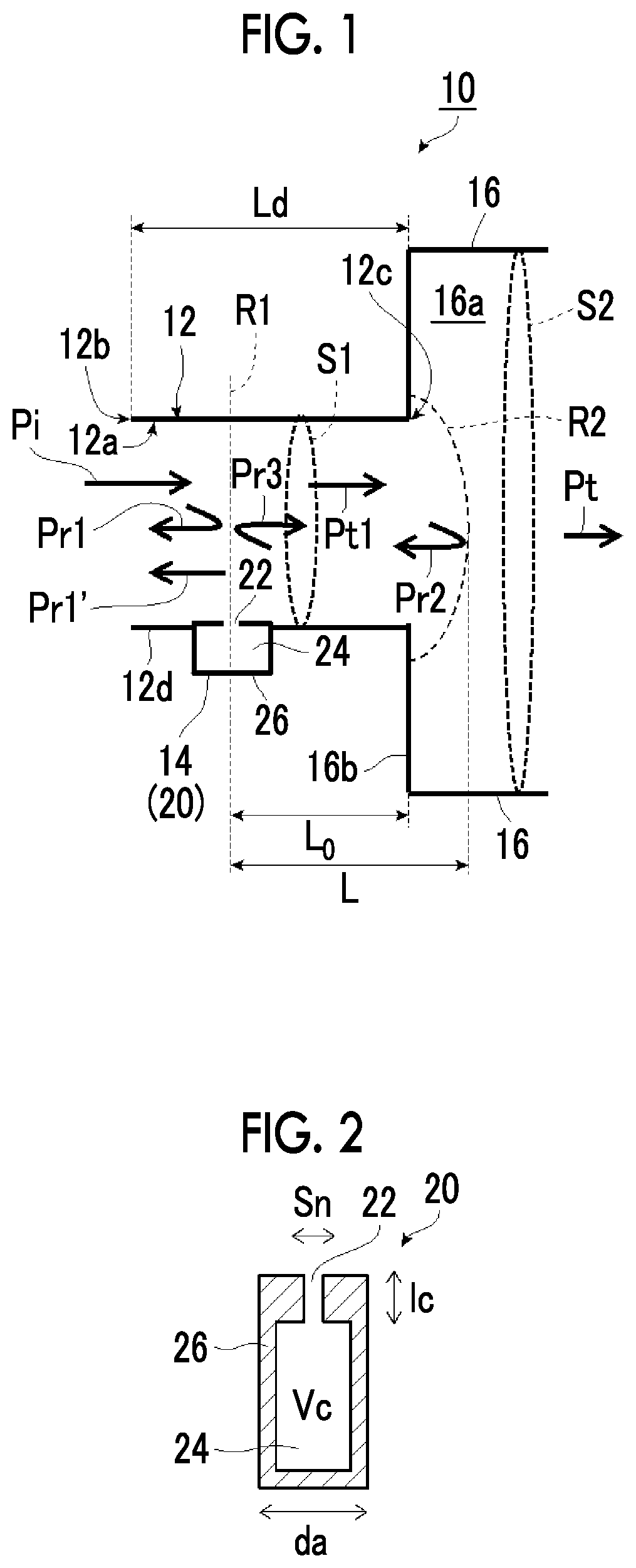
[0237]First, a soundproof structure body 10 according to the embodiment of the present invention illustrated in FIG. 1 was used as Example 1.

[0238]As illustrated in FIG. 1, in the soundproof structure body 10 of Example 1, the Helmholtz resonance structure 20 is used as the resonance structure 14, the resonance hole 22 of the Helmholtz resonance structure 20 and the hollow space 24 of the back surface were installed the wall surface of the tube body 12 to communicate within the opening tube line 12a.

[0239]Various parameters of the soundproof structure body 10 of Example 1 were as follows.

[0240]Length Ld of the tube body 12 is 500 mm.

[0241]A radius r1 of the opening tube line 12a of the tube body 12 is 30 [mm] A cross-sectional area S1 of the opening tube line 12a of the tube body 12 is 2827 [mm2]

[0242]A radius r2 of the tube line 16a of the second tube body 16 is 1000 [mm]

[0243]A cross-sectional area S2 of the tube line 16a of the second tube body 16 is 3.142×10⁶ [mm2].

[0244]Distan...

example 1-1

[0267]Next, in the following procedure, transmission, reflection, and absorption in the soundproof structure body of Example 1-1 of the present invention were simulated using a transfer matrix method. This model is a new model that differs from a model in the related art in that there is a step (with an opening end) having a discontinuous cross-sectional area. In the same manner as described above, Expressions based on the above Expressions (2) to (4) were calculated.

[0268]That is, the reflection coefficient and the transmission coefficient were determined based on the acoustic impedance Z1.

Reflection coefficient r=(Z1−Z0) / (Z1+Z0)  (19)

Transmission coefficient t=2 / (A+B / Z+CZ+D)  (20)

[0269]The reflectance R, the transmittance T, and the absorbance Ab were determined using the reflection coefficient r and the transmission coefficient t obtained in this way.

Reflectance R=r2

Transmittance T=t2×(Sx / S1)

Absorbance Ab=1−R−T

[0270]The reflectance R, the transmittance T, and the absorbance Ab ...

example 1-2

[0298]Example 1-2 was the same as in Example 1, except that the radius of the tube body 12 has a cross-sectional area S1 of 15 mm.

[0299]In Example 1-2, the phase difference θ is also determined in the same way, and the relationship between the difference θ−π and the frequency was obtained. The results are illustrated in FIG. 20.

[0300]As described above, the resonance frequency of the resonance structure 14 can be a frequency at which the imaginary part of the characteristic impedance Zx is 0. This resonance frequency was 2180 Hz in the same manner as in Example 1.

[0301]From a graph in FIG. 20, it can be seen that θ−π≈0.22 [rad.] at the resonance frequency of 2180 Hz. That is, |θ−π| is greater than π / 3, and it can be seen that Example 1-2 satisfies Inequation (1) of claim 1 of the present application.

[0302]Next, in Example 1-2, the reflectance R, the transmittance T, and the absorbance Ab in the acoustic tube having a radius of 15 mm were also determined in the same manner as in Exam...


PUM


Abstract

In a soundproof structure body including a tubular tube body having an opening portion, and a resonance type soundproof structure, in which a phase difference θ, at an upstream of the resonance type soundproof structure, between a reflected wave in the resonance type soundproof structure and a reflected wave of a transmitted wave transmitted through the resonance type soundproof structure and reflected by the opening portion satisfies Inequation |θ−π|≤π / 3 with respect to a resonance frequency of the resonance type soundproof structure. This soundproof structure body can effectively offset a reflected wave from a resonance type soundproof structure body by opening end reflection by appropriately specifying positions of the resonance type soundproof structure and the opening end portion of a duct, a tube line, or the like to improve an absorbance of a single resonance type soundproof structure.

Description

CROSS-REFERENCE TO RELATED APPLICATIONS[0001]This application is a Continuation of PCT International Application No. PCT / JP2019 / 039356 filed on Oct. 4, 2019, which claims priority under 35 U.S.C. § 119(a) to Japanese Patent Application No. 2018-197582 filed on Oct. 19, 2018. The above application is hereby expressly incorporated by reference, in its entirety, into the present application.BACKGROUND OF THE INVENTION1. Field of the Invention[0002]The present invention relates to a soundproof structure body capable of realizing high absorption using a resonance type soundproof structure.2. Description of the Related Art[0003]In the related art, structures such as ducts, tube lines, or the like, which are premised on ensuring air permeability, allow sound together with gas and / or heat to pass. Therefore, noise countermeasures may be required. Thus, in applications for particularly attaching ducts, tube lines, or the like to machines with noise, it is necessary to provide soundproofing i...

Claims


Application Information

Patent Timeline
IPC IPC(8): G10K11/172G10K11/16F24F13/24
CPCG10K11/172B60R13/08F24F13/24G10K11/161F24F2013/245
Inventor OHTSU, AKIHIKOHAKUTA, SHINYASUGAWARA, YOSHIHIROYAMAZOE, SHOGO
Owner FUJIFILM CORP
Why Eureka
Try Eureka