
Method and apparatus for acoustical power transfer and communication using steel wedges

a technology of acoustic power transmission and communication, applied in the field of acoustics, can solve the problems of significant obstacles, inability to connect electrically between segments, and inability to directly access parts of wells and drill strings, and achieve the effect of high transducer launch angl

Active Publication Date: 2019-05-14
RENESSELAER POLYTECHNIC INST
View PDF26 Cites 0 Cited by
  • Summary
  • Abstract
  • Description
  • Claims
  • Application Information

AI Technical Summary

Benefits of technology

This patent describes a method for improving the efficiency of acoustic transmitters and receivers in contact with a metal substrate. The method involves using a wedge made of the same material as the substrate, which helps to reduce the acoustic power reflection coefficient at the interface between the wedge and substrate. By angling the surfaces of the wedge and substrate, and also adding shear waves using a shear-poled transducer coupled to the wedge, the acoustic transfer efficiency is improved. This method can also be used with other materials, such as other metals and metal alloys.

Problems solved by technology

Often, portions of the well and drill string are not directly accessible via a direct electrical connection.
For example, there may be segments that are disjointed and sealed off from each other, making electrical connection between the segments impossible.
Since it is desirable to obtain data from deep within wells, passage of the data through these obstacles is a significant issue.
Although guided wave modes in the substrate have been more extensively studied than bulk waves, wedge-introduced bulk waves have shown the potential to outperform them in some situations.
For example, there may be segments that are disjointed and sealed off from each other, making electrical connection between the segments impossible.

Method used


Image

  • Method and apparatus for acoustical power transfer and communication using steel wedges
  • Method and apparatus for acoustical power transfer and communication using steel wedges
  • Method and apparatus for acoustical power transfer and communication using steel wedges

Examples


Embodiment Construction

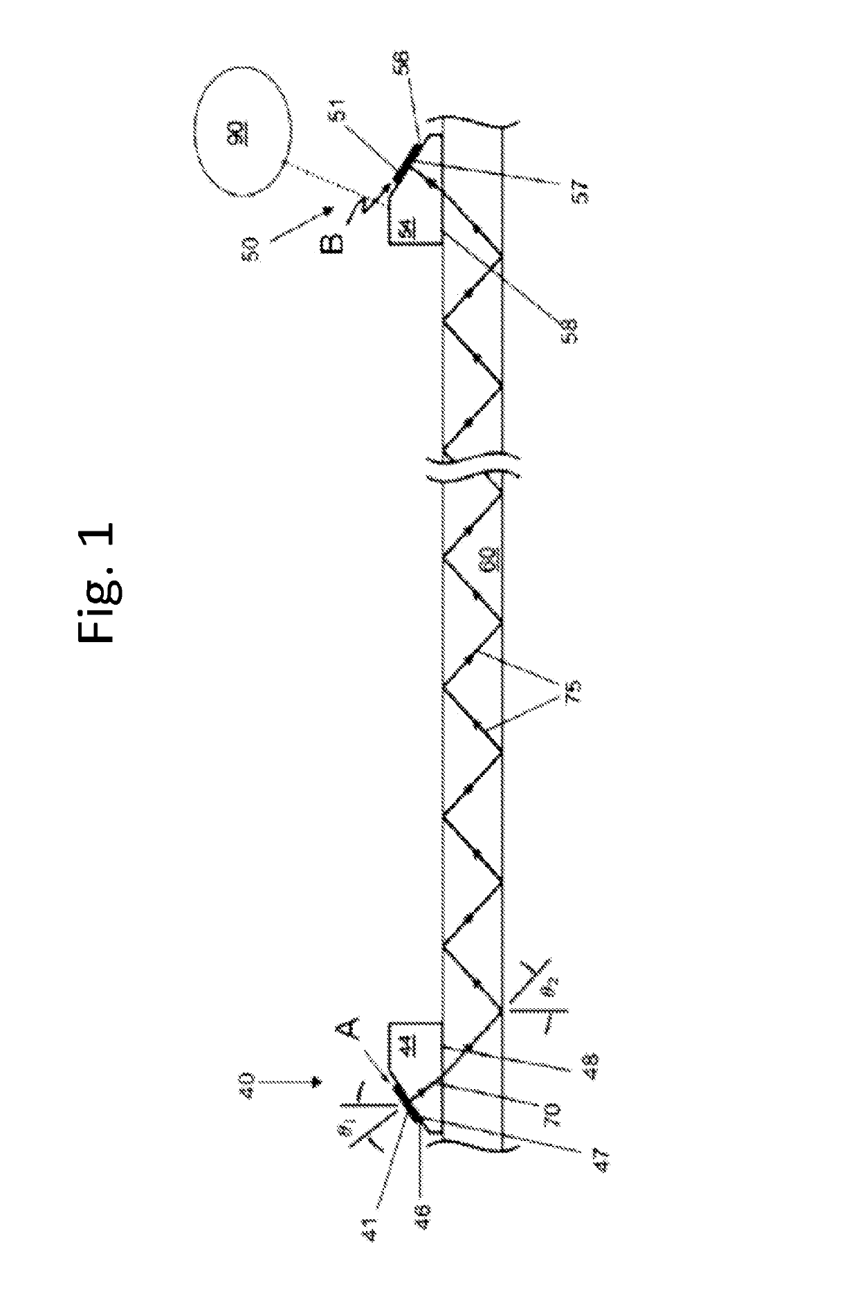
[0155]FIG. 1 is a schematic illustration of a transducers / wedges / pipe substrate arraignment. This embodiment differs from a most-preferred version of the invention in that the wedges / blocks 44,54 and the substrate 80 are not made of identical materials. Therefore, the angle of the wave is depicted as changing as it passed into and then back out of the substrate 80. Nevertheless the FIG. 1 illustration is helpful to understand the different elements of acoustic wedge transmission systems. In particular, each transducer typically includes a generally planar face 47,57. Each transition wedge preferably has at least one slanted edge 46,56. The angles of the planar faces 47,57 of the transducer(s) and of the slanted edge(s) 46,56 of the blocks / wedges / transition wedges 44,54 affect the function of the acoustic channels.

[0156]FIG. 27 is a simplified schematic illustration of a transducers / wedges / pipe substrate arraignment of the present invention wherein the transducer faces 47,57 and slan...


PUM


Abstract

Systems and methods for transmitting power and information using acoustic energy produced by transducers are provided. The systems have particular application for powering and communication with electronics through drilling and pipe systems. Pairs of acoustic wedges holding transducers are provided for sending energy and information through a substrate which may be a steel pipe. Each wedge has an angled transducer which can be used to produce shear waves. The waves propagate through the substrate and are received by a second acoustic wedge. The shear waves, on reaching the second acoustic wedge, are converted back into electrical signals by a second transducer. Tangential shear waves, high, shallow wave transmission angles, and direct steel-steel bonding between wedges and substrates may be used.

Description

RELATED APPLICATIONS[0001]This application claims the benefit of U.S. Provisional Patent Application No. 61 / 944,916, filed Feb. 26, 2014, which is incorporated by reference herein in its entirety.FIELD AND BACKGROUND OF THE INVENTION[0002]The present invention relates generally to the field of acoustics, and in particular to transducers, to communication and power transmission using vibrations, and to taking sensor readings in deep wells.[0003]The present invention includes improvements on the inventor's own previous work as described in International Patent Application PCT / US2013 / 056143 (published as WO2014 / 035785), U.S. Patent Application 61 / 693,366, and U.S. Patent Application 61 / 693,370, all of which are incorporated herein by reference, and which are intended for use with the present improvement and invention. These references disclose systems and methods for transmitting power and information using acoustic energy, typically through drilling and pipe systems. Pairs of acoustic...

Claims


Application Information

Patent Timeline
Patent Type & Authority Patents(United States)
IPC IPC(8): G01J3/30E21B47/16H04B11/00H02J50/15
CPCE21B47/16H04B11/00H02J50/15
Inventor SCARTON, HENRY A.SAULNIER, GARY J.WILT, KYLE R.LITMAN, R. BENJAMIN
Owner RENESSELAER POLYTECHNIC INST
Learn More