Drive circuit for a permanent magnet motor

a technology of driving circuit and permanent magnet motor, which is applied in the direction of dynamo-electric machines, synchronous motor starters, starter arrangements, etc., can solve the problems of motor not running on a relatively high operating point, low efficiency, and low operation efficiency of fans, water pumps

Inactive Publication Date: 2019-02-19
JOHNSON ELECTRIC SA
View PDF7 Cites 0 Cited by
  • Summary
  • Abstract
  • Description
  • Claims
  • Application Information

AI Technical Summary

Benefits of technology

[0005]Accordingly, in one aspect thereof, the present invention provides a drive circuit for an electric motor comprising a stator and a permanent magnet rotor rotatable with respect to the stator, the stator comprising a stator core and a stator coil wound on the stator core, the drive circuit comprising: a controllable bidirectional AC switch connected in series with the stator coil between two terminals for connecting to an AC power supply; a first position sensor and a second position sensor for detecting positions of the magnetic poles of the permanent magnet rotor; and a voltage regulating circuit connected between the two terminals and the controllable bidirectional AC switch and configured to supply power to the first sensor during positive cycle of the AC power supply and to the second position sensor during negative cycle of the AC power supply such that the controllable bidirectional AC switch is switched between a conductive state and a non-conductive state in a predetermined manner, thus enabling the stator coil to urge the rotor only in a fixed direction during the start-up phase of operation of the motor.

Problems solved by technology

For guaranteeing the starting of the traditional synchronous motor, the starting point of the motor is usually set to be lower, which results in that the motor cannot run on a relatively high operating point, and therefore efficiency is lower.
Accordingly, in applications of fans, water pumps, etc., the impeller driven by the rotor adopts straight type radial blade usually, which results in the lower operational efficiency of the fans, water pumps, etc.

Method used


Image

  • Drive circuit for a permanent magnet motor
  • Drive circuit for a permanent magnet motor
  • Drive circuit for a permanent magnet motor

Examples


Embodiment Construction

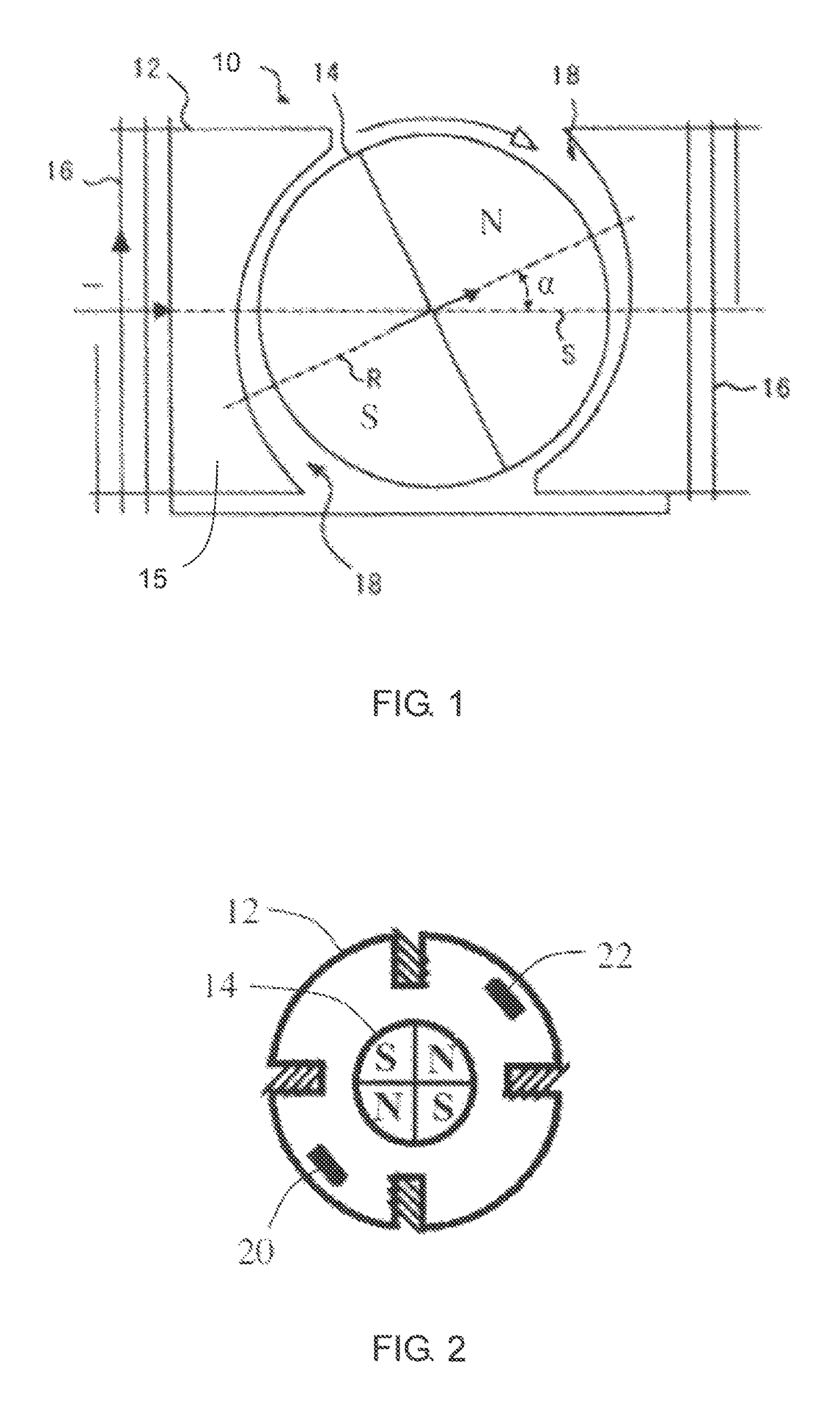
[0026]FIG. 1 is a schematic diagram of a synchronous motor in accordance with an embodiment of the present invention. The synchronous motor 10 comprises a stator 12, and a permanent magnet rotor 14 rotatably disposed between the magnetic poles of the stator 12. The stator 12 has a stator core 15 and a stator winding 16 wound on the stator core. The rotor 14 includes at least one permanent magnet forming at least one pair of permanent magnetic poles with opposite polarities. The rotor 14 operates at a constant rotational speed of 60 f / p during a steady state phase of operate when the stator winding 16 and an AC power supply are connected in series, where f is a frequency of the AC power supply and p is the number of pole pairs of the rotor.

[0027]A non-uniform air gap 18 is formed between the magnetic poles of the stator 12 and the magnetic poles of the rotor 14, thus enabling the polar axis R of the rotor 14 to be offset by an angle α with respect to the central axis S of the stator ...


PUM


Abstract

A drive circuit for an electric motor having a wound stator and a permanent magnet rotor, includes a controllable bidirectional AC switch connected in series with a stator winding between two terminals for connecting to an AC power supply. First and second position sensors detect the position of magnetic poles of the rotor. A voltage regulating circuit is connected between the two terminals and the controllable bidirectional AC switch and configured to supply power to the first sensor during the positive cycle and to the second position sensor during the negative cycle of the AC power supply such that the controllable bidirectional AC switch is switched between a conductive state and a non-conductive state in a preset manner, thus enabling the stator to rotate the rotor in only one predetermined direction during start-up.

Description

CROSS REFERENCE TO RELATED APPLICATIONS[0001]This non-provisional patent application claims priority under 35 U. S. C. § 119(a) from Patent Application No. 201410390592. 2 filed in The People's Republic of China on Aug. 8, 2014, and from Patent Application No. 201410404755.8 filed in The People's Republic of China on Aug. 15, 2014, the entire contents of which are hereby incorporated by reference.FIELD OF THE INVENTION[0002]The present invention relates to a drive circuit for a permanent magnet motor, and is particularly suitable for small motors for use in low-power fans, water pumps, etc.BACKGROUND OF THE INVENTION[0003]During the starting process of the synchronous motor, the electromagnet of the stator produces an alternating magnetic field and drags the permanent magnet rotor to oscillate. If the rotor obtains enough kinetic energy, the oscillation amplitude of the rotor will constantly increase, which finally accelerates the rotation of the rotor rapidly to be synchronous with...

Claims


Application Information

Patent Timeline
Patent Type & Authority Patents(United States)
IPC IPC(8): H02K29/03H02P1/46H02P1/22H02P7/06H02P7/295H02P6/22
CPCH02P1/465H02P6/22H02P7/295H02P7/066H02P2207/05
Inventor LI, YUESUN, CHI PINGLIU, BAO TINGWANG, EN HUIXIN, FEIYEUNG, SHING HINYANG, XIU WENCUI, YAN YUNHUANG, SHU JUAN
Owner JOHNSON ELECTRIC SA
Why Eureka
Try Eureka