Eureka AIR delivers breakthrough ideas for toughest innovation challenges, trusted by R&D personnel around the world.

State of deterioration or state of charges estimating apparatus for secondary battery

a secondary battery and state of deterioration technology, applied in secondary cell servicing/maintenance, instruments, electrochemical generators, etc., can solve the problem of lithium ions in the electrolytic solution concentration, and achieve the effect of extending the life of the secondary battery, and improving accuracy in estimating the deterioration sta

Active Publication Date: 2019-02-19
TOYOTA JIDOSHA KK
View PDF22 Cites 3 Cited by
  • Summary
  • Abstract
  • Description
  • Claims
  • Application Information

AI Technical Summary

Benefits of technology

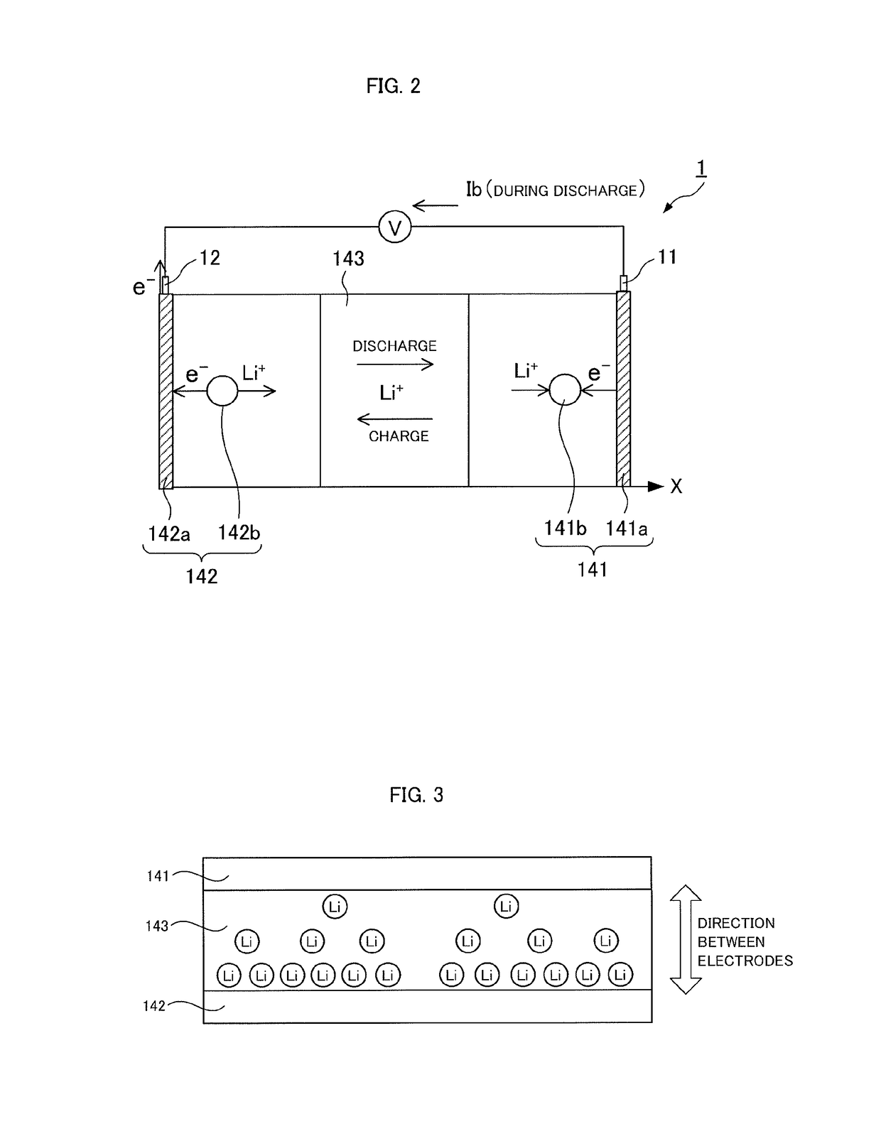
[0012]The deterioration state or the charge state of the secondary battery depends not only on the average ion concentration but also on an ion concentration imbalance between the positive electrode and the negative electrode. The accuracy in estimating the deterioration state and the charge state can be improved by finding not only the average ion concentration between the electrodes but also the ion concentration imbalance between the electrodes.
[0014]The deterioration state of the secondary battery depends not only on the average ion concentration but also on an ion concentration imbalance in a plane (in an electrode plane) in which the positive electrode and the negative electrode are opposite to each other. The accuracy in estimating the deterioration state can be improved by finding not only the average ion concentration between the electrodes but also the ion concentration imbalance in the electrode plane.
[0016]When the average ion concentration between the electrodes, the ion concentration imbalance between the electrodes, and the ion concentration imbalance in the electrode plane are obtained, the accuracy in estimating the deterioration state can be further improved. The controller can limit an output from or an input to the secondary battery when the deterioration state is estimated and a parameter specifying the estimated deterioration state is larger than a threshold value.
[0017]This can prevent an increase in the parameter specifying the deterioration state to extend the life of the secondary battery. When the accuracy in estimating the deterioration state can be improved as described above, excessive limitation of the input to and output from the secondary battery can be avoided to improve the input / output characteristics of the secondary battery. In addition, excessive relaxation of the input to and output from the secondary battery can also be prevented to avoid extremely advanced deterioration of the secondary battery. As a result, the life of the secondary battery can be extended.

Problems solved by technology

When the secondary battery is discharged, the lithium ions in the electrolytic solution move from a negative electrode toward a positive electrode to produce the imbalance in the concentration of the lithium ions in the electrolytic solution.

Method used


Image

  • State of deterioration or state of charges estimating apparatus for secondary battery
  • State of deterioration or state of charges estimating apparatus for secondary battery
  • State of deterioration or state of charges estimating apparatus for secondary battery

Examples


embodiment 1

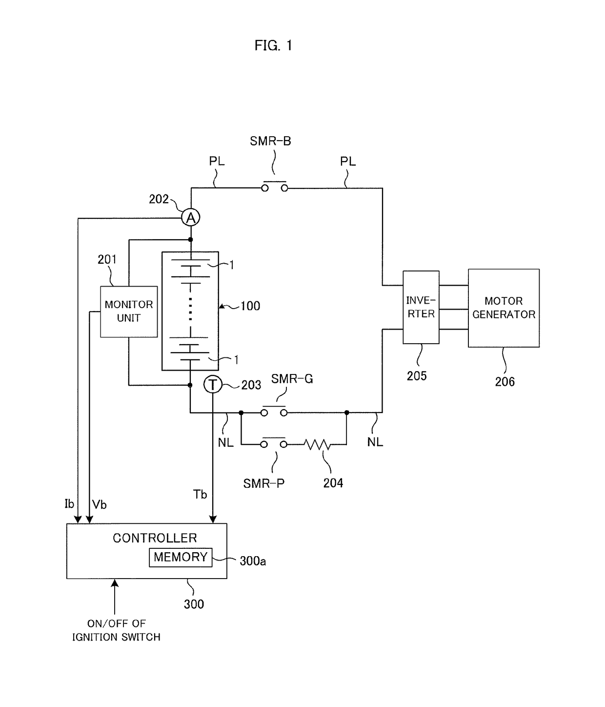
[0045]FIG. 1 is a diagram showing the configuration of a battery system which is Embodiment 1. The battery system shown in FIG. 1 can be mounted on a vehicle. Examples of the vehicle include a HV (Hybrid Vehicle), a PHV (Plug-in Hybrid Vehicle), and an EV (Electric Vehicle). The present invention is applicable to any system that is used to charge and discharge a secondary battery.

[0046]The HV includes not only an assembled battery, later described, but also another power source such as an internal-combustion engine or a fuel cell, as the power source for running of the vehicle. The PHV is a variant of the HV in which the assembled battery can be charged with electric power from an external power source. The EV includes only the assembled battery as the power source of the vehicle and allows charge of the assembled battery by receiving electric power from the external power source. The external power source is a power source (for example, a commercial power source) provided outside a...

embodiment 2

[0201]Embodiment 2 of the present invention will hereinafter be described. In the present embodiment, a battery model, later described, is used to estimate the internal state and the SOC of a secondary battery 1. In the present embodiment, components identical to those described in Embodiment 1 are designated with the same reference numerals, and detailed description thereof is omitted.

[0202]First, the battery model used in the present embodiment is described. A basic battery model expression is represented by basic equations including the following expressions (19) to (29). FIG. 14 shows a list of variables and constants used in the battery model expression.

[0203]In the variables and constants in the model expression described below, a subscript e means a value in an electrolytic solution and a subscript s means a value in an active material. A subscript j makes a distinction between a positive electrode and a negative electrode, wherein j equal to 1 means a value in the positive e...


PUM

PropertyMeasurementUnit
charge stateaaaaaaaaaa
concentrationaaaaaaaaaa
ion concentrationaaaaaaaaaa

Abstract

A battery system includes a chargeable and dischargeable secondary battery and a controller that estimates the deterioration state or the charge state of the secondary battery. When estimating the deterioration state or the charge state, the controller uses an average ion concentration between a positive electrode and a negative electrode. The average ion concentration varies depending on an electric current flowing through the secondary battery. The average ion concentration between the electrodes can be calculated with a computing expression that includes a surface pressure of the secondary battery as a variable. The surface pressure of the secondary battery can be detected by a pressure sensor. The surface pressure of the secondary battery can also be estimated from an electric current flowing through the secondary battery.

Description

CROSS REFERENCE TO RELATED APPLICATIONS[0001]This application is a National Stage of International Application No. PCT / JP2013 / 000581 filed Feb. 1, 2013, the contents of all of which is incorporated herein by reference in its entirety.TECHNICAL FIELD[0002]The present invention relates to a battery system in which the deterioration state and the charge state of a secondary battery are estimated.BACKGROUND ART[0003]Patent Document 1 has described that an evaluation value is calculated in accordance with a change of imbalance in concentration of lithium ions in an electrolytic solution, and the output from the secondary battery is controlled on the basis of the evaluation value. The evaluation value is a value for evaluating the deterioration of the secondary battery.[0004]When the secondary battery is discharged, the lithium ions in the electrolytic solution move from a negative electrode toward a positive electrode to produce the imbalance in the concentration of the lithium ions in t...

Claims


Application Information

Patent Timeline
Patent Type & Authority Patents(United States)
IPC IPC(8): G01R31/36H02J7/00H01M10/48
CPCG01R31/3648H02J7/00G01R31/382G01R31/392H01M10/486H01M10/44Y02E60/10
Inventor KAIYA, HIROYUKITAKAHASHI, KENJINISHI, YUJITASHIRO, HIROKI
Owner TOYOTA JIDOSHA KK
Why Eureka
Eureka Blog
Learn More