Eureka AIR delivers breakthrough ideas for toughest innovation challenges, trusted by R&D personnel around the world.

Lifting assembly for a lift truck, and lift truck

a technology for lifting assembly and lift truck, which is applied in the direction of gearing, belt/chain/gearing, lifting device, etc., can solve the problems of not being able to induce the lifting chain enough, affecting the operation of the lifting chain, and striking other components, etc., to eliminate a significant source of noise, reduce noise, and reduce nois

Active Publication Date: 2019-02-19
JUNGHEINRICH AG
View PDF20 Cites 0 Cited by
  • Summary
  • Abstract
  • Description
  • Claims
  • Application Information

AI Technical Summary

Benefits of technology

[0008]The lifting assembly provides a design where the lifting chain produces a particularly low noise emission during the operation. According to one embodiment, a lifting assembly of the indicated type includes at least one tensioning component that applies initial tension and is arranged on the mast frame between the connecting point and deflection point of the lifting chain, and deflects the lifting chain out of its direct connecting line defined as a straight line between the connecting point and deflection point. The lifting chain is pushed out of this direct connecting line by the tensioning component, and the lifting chain lies against the tensioning component under initial tension. By means of this solution, the noise emission in the lifting assembly which arises while driving from striking lifting chains is reduced as the lifting chains are prevented from striking the profiles and adjacent components, which eliminates a significant source of noise in a lifting truck or a forklift.
[0009]The goal of noise reduction is achieved in that the lifting chain is prevented from oscillating freely in normal operation by the provided tensioning component. The free oscillation of the lifting chain is prevented by pretensioning the lifting chain and shortening the oscillation length of the lifting chain. The oscillating length of the lifting chain is the length of the lifting chain between the attachment point and the tensioning component and the deflection point and the tensioning component. The initial tension and the shortening of the oscillating length of the lifting chain is realized by deflecting the lifting chain out of the direct connecting line between the connecting point and the deflection point by means of a tensioning component, which will be termed a lifting chain stabilizer in this context.
[0012]By means of the lifting chain stabilizer provided, a shortening of the oscillation length of the corresponding lifting chain is achieved, which causes the oscillating chain to possess a higher frequency. At higher frequencies, the amplitudes of the corresponding oscillations are less so that the lifting chain automatically strikes against the adjacent components less frequently or not at all (and less forcefully as well) due to the smaller excursions (amplitudes) of the lifting chain.
[0016]In one embodiment, the lifting chain stabilizer is designed in the shape of a block. In particular, it has a contact surface against which the lifting chain lies. Since the lifting chain stabilizer moves together with the associated mast frame and the lifting chain, no relative movement occurs between the contact surface of the lifting chain stabilizer and the lifting chain. This results in very little or no wear of the contact surface.
[0023]In one embodiment, the lifting chain stabilizer can form a guide for the lifting chain. As already noted, no relative movement occurs between the lifting chain and the compliant lifting chain stabilizer. Accordingly, the guide prevents the lifting chain from jumping to the side of the lifting chain stabilizer. For this purpose, the compliant lifting chain stabilizer can possess edges arranged on the side of the lifting chain, preferably next to a contact surface for the lifting chain, which prevent the lifting chain from jumping off to the side of the lifting chain stabilizer.
[0024]In one embodiment, the lifting chain stabilizer is adhered to the mast frame. The advantage of adhesion is that no mechanical fasteners need to be incorporated on the mast profile. Adhesion also offers sufficient retention due to the initial tension on the lifting chain stabilizer from the lifting chain.

Problems solved by technology

As a result, the lifting chain only lifts off of its predetermined contact points and can strike other components in the event of major jarring.
In addition, the lifting chain can only lift off to one side due to the deflection of the lifting chain by the lifting chain stabilizer.
The normal jarring caused by driving the lift truck is not enough to sufficiently induce the lifting chain to strike against other components.

Method used


Image

  • Lifting assembly for a lift truck, and lift truck
  • Lifting assembly for a lift truck, and lift truck
  • Lifting assembly for a lift truck, and lift truck

Examples


Embodiment Construction

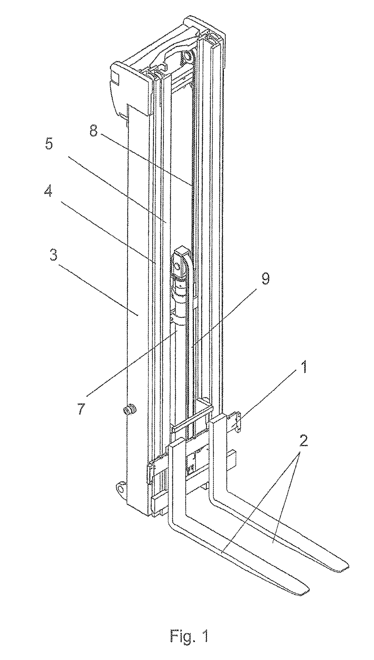
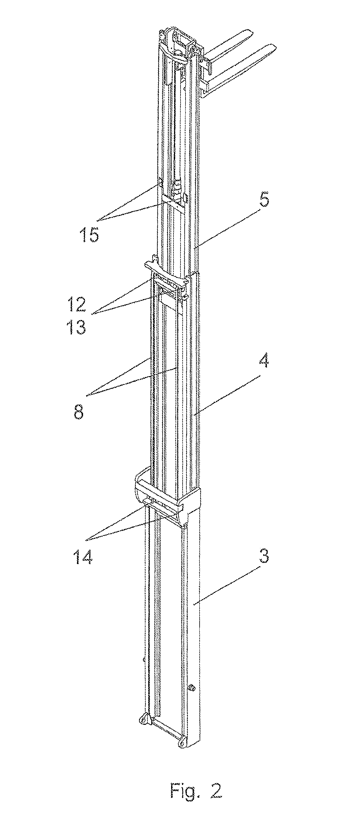
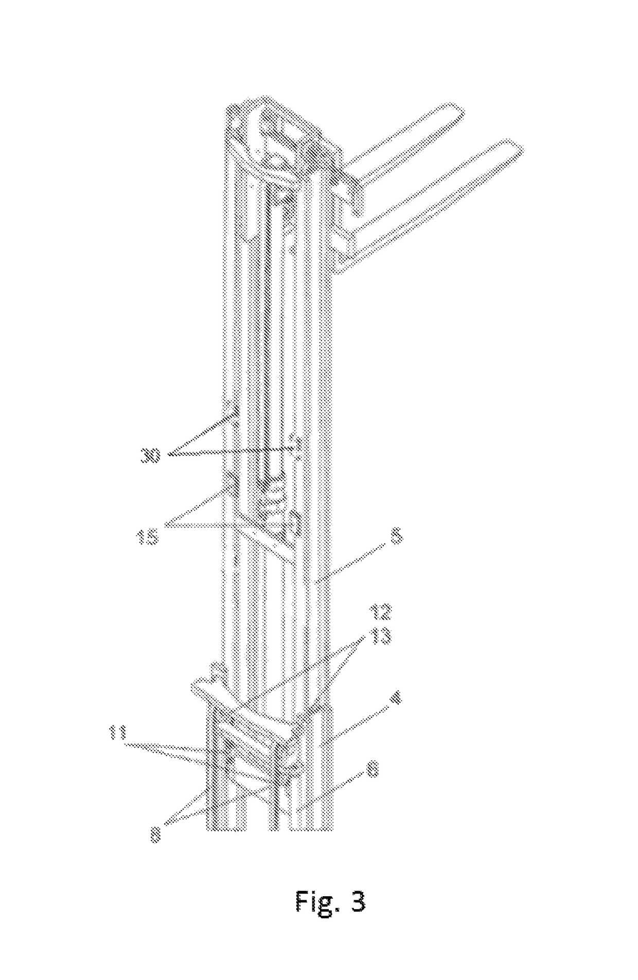
[0034]The lifting mast depicted in FIG. 1 of a lifting assembly for a forklift is designed as a triple mast, and possesses a lifting mast frame 4 which is lifted by two mast lifting cylinders 6 (shown in FIG. 3), an inner mast frame 5 which is lifted with two mast lifting chains 8, and an outer column 3. The corresponding mast frames are mounted within each other and guided within each other. Furthermore, the lifting mast possesses a load part 1 with fork arms 2 on which a payload to be lifted or lowered is arranged. The load part 1 is lifted with assistance of a free lift cylinder 7 and a free lift chain 9. The mast lifting chains 8 are fastened at the bottom end of the inner mast frame 5 to connecting points 11 (see FIG. 3). At the top end of the middle mast frame 4, they are deflected at deflection points 12 across chain rollers 13 as shown in FIG. 2. The other end of the respective lifting chain 8 is fastened within the column 3 at a connecting point 14 as shown in FIG. 2.

[0035]...


PUM


Abstract

A lifting assembly for a lift truck with a lifting mast having at least one mast frame and a load part, as well as a lift drive having at least one lifting chain that lifts the mast frame, is attached to the mast frame at a connecting point and is guided across a deflection point. The lifting assembly includes at least one tensioning component that is arranged on the mast frame between the connecting point and deflection point of the lifting chain.

Description

CROSS REFERENCE TO RELATED APPLICATION[0001]This application is based upon and claims priority under relevant sections of 35 USC § 119 to German Patent Application No. 10 2015 102 402.0, filed Feb. 20, 2015, the entire contents of which are hereby incorporated by reference.BACKGROUND OF THE INVENTION[0002]The present invention relates to a lifting assembly for a lift truck with a lifting mast having at least one mast frame and a load part, as well as a lift drive having at least one lifting chain that lifts the mast frame. The lifting chain is attached to the mast frame at a connecting point and is guided across a deflection point. Such lifting assemblies are used for lift trucks, in particular fork lifts.[0003]Lift trucks, or respectively forklifts, with a lifting assembly have lifting masts which make it possible to lift and lower payloads. The lifting masts possess a plurality of mast frames which are mounted and guided within each other, as well as a load part which is usually p...

Claims


Application Information

Patent Timeline
Patent Type & Authority Patents(United States)
IPC IPC(8): B66F9/08F16H7/08B66F9/07
CPCB66F9/08F16H7/08B66F9/07
Inventor MELOCH, PIOTRFISCHER, KAI
Owner JUNGHEINRICH AG
Why Eureka
Eureka Blog
Learn More