
Drug delivery device

a delivery device and drug technology, applied in the direction of intravenous devices, other medical devices, infusion needles, etc., can solve the problems of insufficient audible indication, the mechanism used to provide an audible indication,

Active Publication Date: 2019-02-19
OVAL MEDICAL TECH
View PDF14 Cites 12 Cited by
  • Summary
  • Abstract
  • Description
  • Claims
  • Application Information

AI Technical Summary

Benefits of technology

The patent text describes a mechanism for providing a loud audible indication when a drug delivery device is complete. Previous mechanisms had limited noise because they relied on a portion of the drive element. The new solution uses a stored energy source to drive two parts of a multi-part drive mechanism against each other when they reach a predetermined position within the device. This allows for a much greater noise as the parts can be made rigid and may be driven against each other at high speed. The patent text also explains the significance of a closure seal which prevents deterioration or contamination of a drug in a container against foreseeable external factors in storage. This ensures the safety, identity, strength, quality, sterility and / or purity of a drug in a container in compliance with official, regulatory or established requirements.

Problems solved by technology

Previous mechanisms used to provide an audible indication of completion of drug delivery in drug delivery devices have suffered from the problem that the audible indication has not been loud enough.

Method used


Image

  • Drug delivery device
  • Drug delivery device
  • Drug delivery device

Examples


first embodiment

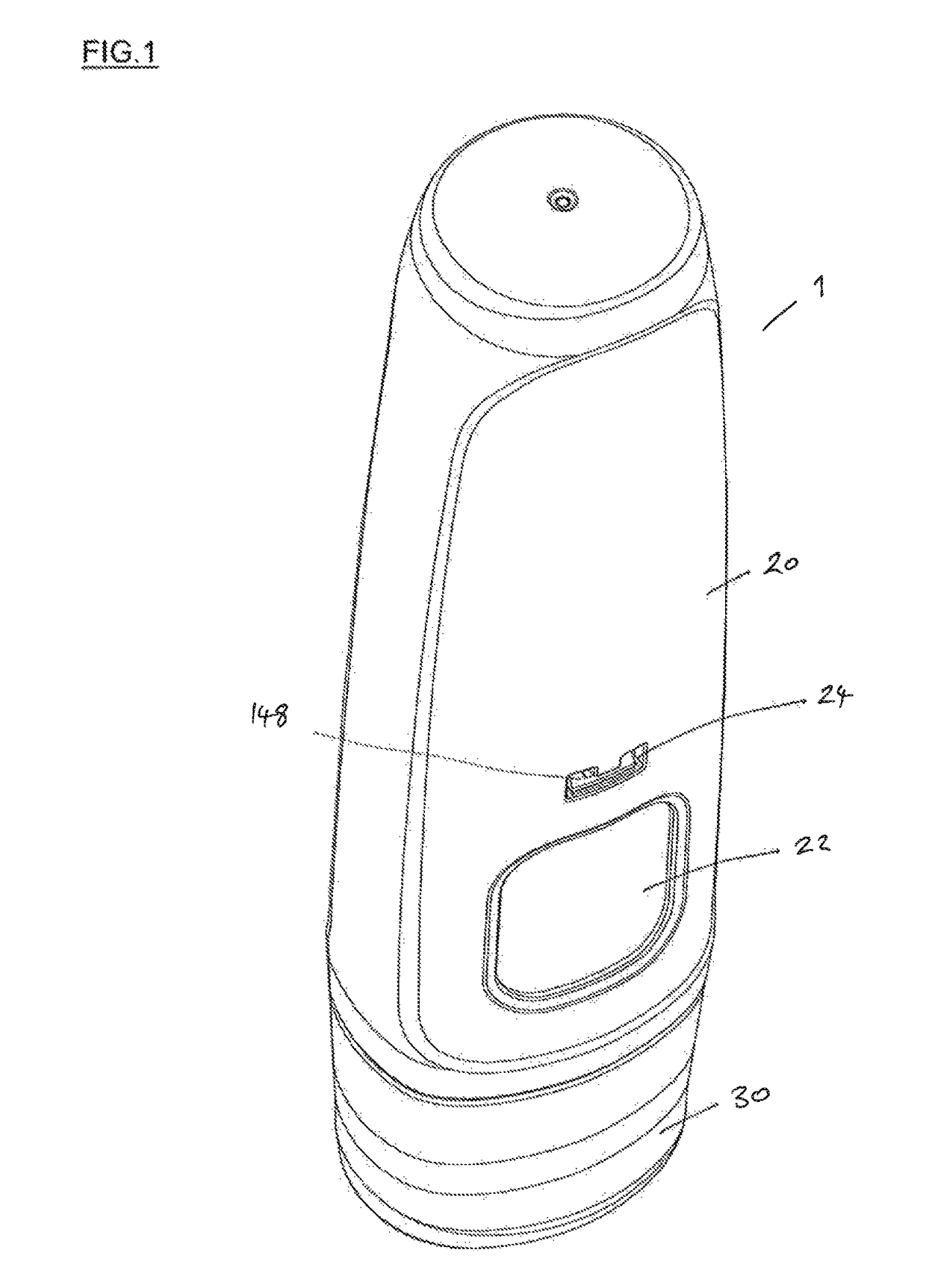
[0191]FIG. 1 is a perspective view of an autoinjector 1 in accordance with the invention, before use. The autoinjector comprises an outer housing 20, having a viewing window 22 through which a drug within the autoinjector can be inspected. A cap 30 is provided to cover the end of the device through which the needle passes during operation and to prevent inadvertent activation of the device. The autoinjector is compact, being approximately 10 cm long and fits easily in a user's hand.

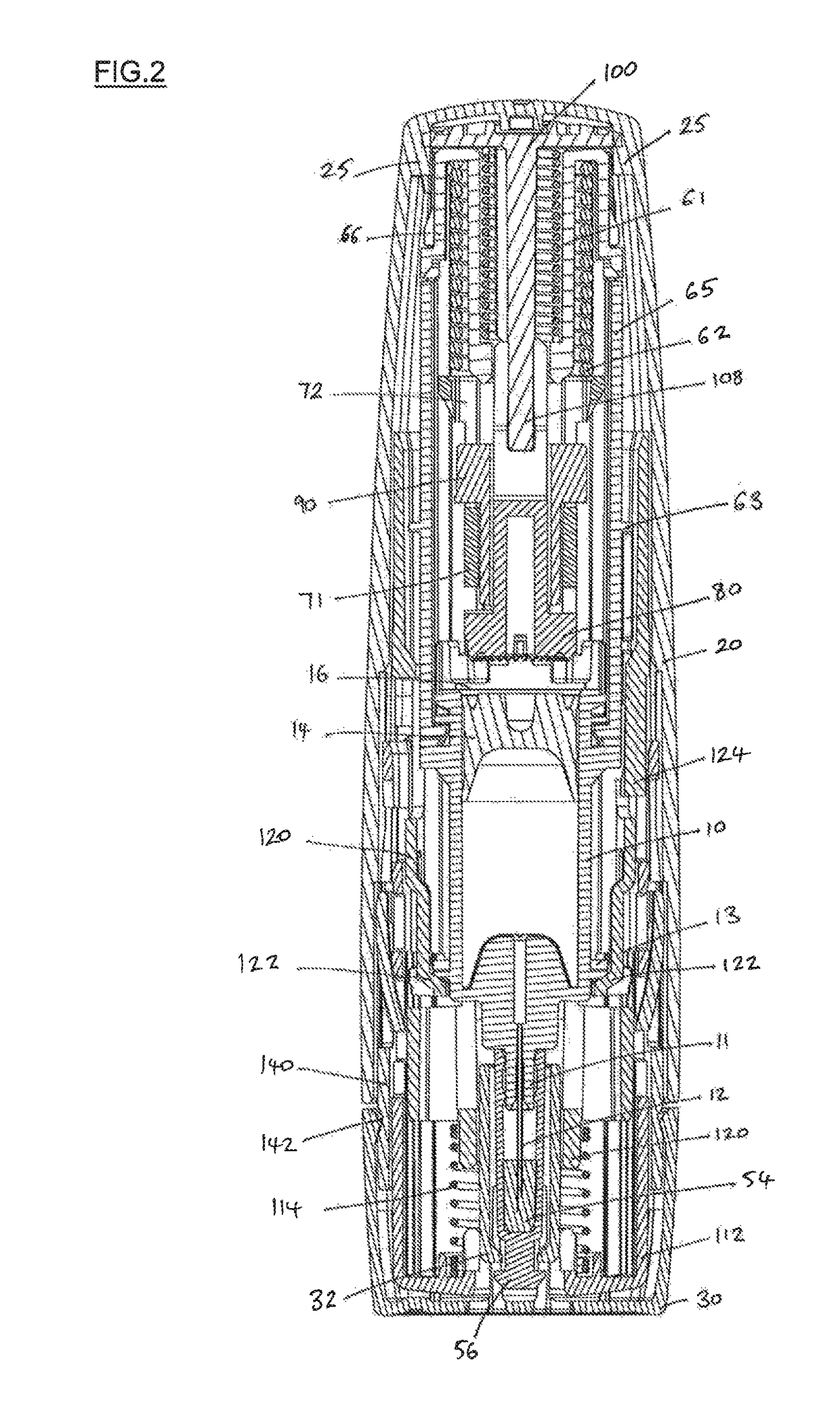
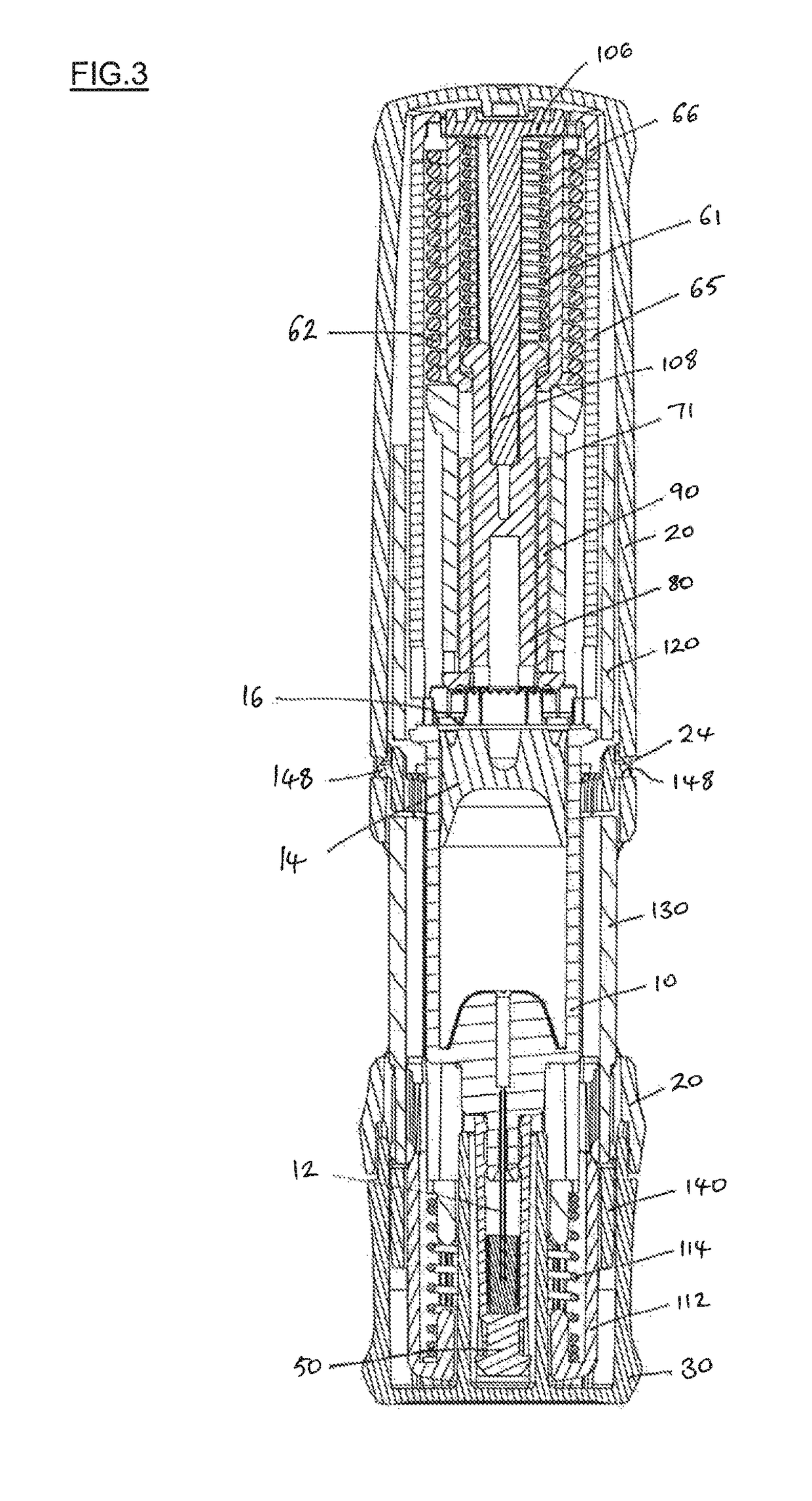
[0192]FIG. 2 is a cross-sectional view through the autoinjector 1 of FIG. 1. FIG. 3 is a second cross-sectional view through the autoinjector of FIG. 1, at 90 degrees to the cross-section of FIG. 2.

[0193]The autoinjector 1 shown in FIGS. 1, 2 and 3 comprises a drug container assembly (shown in FIGS. 4a and 4b), a powerpack assembly (shown partially in FIGS. 6a, 6b and 7) including an end of delivery noise generating mechanism (shown in FIGS. 8 and 9), an internal housing (shown in FIG. 11), herein referre...

second embodiment

[0242]FIG. 18 is a perspective view of an autoinjector 201 in accordance with the invention, before use. The autoinjector 201 comprises an outer housing 220, having a viewing window 222 through which a drug within the autoinjector can be inspected. A cap 230 is provided to cover the needle insertion end of the device and to prevent inadvertent activation of the device. The autoinjector is compact, being approximately 10 cm long and fits easily in a user's hand.

[0243]FIG. 19 is a cross-sectional view through the autoinjector 201 of FIG. 19. FIG. 20 is a second cross-sectional view through the autoinjector of FIG. 19, at 90 degrees to the cross-section of FIG. 19.

[0244]The autoinjector 201 shown in FIGS. 18, 19 and 20 comprises a drug container assembly (shown in FIG. 21), a powerpack assembly including a powerpack housing 264 (as shown in FIG. 27), a drive member 270 and insertion and drive springs 260, 262, an internal housing (shown in FIG. 23), herein referred to as the chassis, a...


PUM


Abstract

There is provided drug delivery devices including a drug container assembly with a needle and automatic needle insertion and drug delivery mechanisms. Aspects of the devices described include a noise-generation mechanism to indicate the completion of drug delivery, a mechanism for triggering drug delivery following needle insertion, front-end activation of the device and a safety mechanism for covering the needle after use and methods of assembly of the devices.

Description

CROSS-REFERENCE TO RELATED APPLICATIONS[0001]This application is a U.S. National Stage Application under 35 U.S.C. § 371 of International Application No. PCT / GB2014 / 052282, filed Jul. 25, 2014, titled DRUG DELIVERY DEVICE, which claims priority to United Kingdom Patent Application No. GB 1313782.3, filed Aug. 1, 2013. International Application No. PCT / GB2014 / 052282 is incorporated by reference herein in its entirety.FIELD OF THE INVENTION[0002]The present invention relates to devices for administering drugs to patients, and in particular to autoinjectors.BACKGROUND TO THE INVENTION[0003]An autoinjector is a drug delivery device that contains a medical, therapeutic, diagnostic, pharmaceutical or cosmetic compound (drug) before it is administered, and which is used to administer the compound through the skin of the patient via a hollow needle. Autoinjectors may be used by the patient themselves or by a different user, and may be used to administer drugs to animals.[0004]Autoinjectors ...

Claims


Application Information

Patent Timeline
Patent Type & Authority Patents(United States)
IPC IPC(8): A61M5/20A61M5/315A61M5/32A61M5/36A61M5/50A61M5/31
CPCA61M5/2033A61M5/3157A61M5/3202A61M5/36A61M5/50A61M5/3204A61M2205/581A61M2005/3109A61M2005/3117A61M2005/3121A61M5/002A61M5/1782A61M5/2459A61M2005/31521
Inventor CEREDA, VALERIO LELIOLAMBLE, RALPH GEORGESAVILL, MICHAEL CHARLESMCROBERT WHITE, SUSANNA ELIZABETHYOUNG, MARTYN JAMESYOUNG, MATTHEW EGERTONLAWSON, JONATHAN
Owner OVAL MEDICAL TECH
Learn More