
Traffic monitoring

a technology for traffic monitoring and apparatus, applied in the direction of subsonic/sonic/ultrasonic wave measurement, measurement devices, instruments, etc., can solve the problems of difficult access for repair or maintenance, more work to be installed, and the surface of the sensor strip or hose will be subject to relatively severe wear and tear, and the sensor will be more difficult to maintain

Active Publication Date: 2019-02-05
OPTASENSE HLDG LTD
View PDF22 Cites 14 Cited by
  • Summary
  • Abstract
  • Description
  • Claims
  • Application Information

AI Technical Summary

Benefits of technology

The invention provides new ways to monitor traffic, especially road traffic, that help to fix some of the problems that previously existed.

Problems solved by technology

Sensor strips or hoses laid across the surface of a road will be subject to relatively severe wear and tear requiring robust sensors and / or regular maintenance.
Sensors embedded within a highway will be less exposed but will typically require more work to be installed and are much harder to access for repair or maintenance.
The sensors are embedded within the carriageway with the associated costs and inconvenience of installation and difficulty of maintenance.
Magnetic sensors using embedded magnetic detectors have also been proposed but have similar issues to inductive sensors.
Such sensors may be relatively expensive however and need to be mounted with a good view of the road to be monitored which, as mentioned may require the presence of overhead structures—which may be not be available in various parts of the network.
However such methods are likely to be of limited use in low traffic volumes, may not provide enough accuracy to determine lane usage of a multi-lane road and may struggle in tunnels or mountainous regions where the GPS signals may be lost.

Method used


Image

  • Traffic monitoring
  • Traffic monitoring

Examples


Embodiment Construction

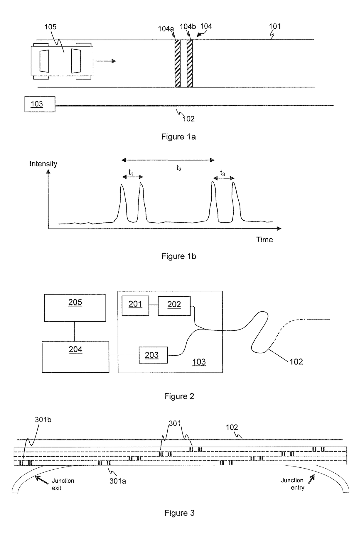
[0045]Embodiments of the present invention relate to traffic monitoring apparatus and methods. One embodiment of the invention relates to a system for monitoring traffic movement on a road comprising a distributed fibre optic sensor apparatus for interrogating an optical fibre with optical radiation to provide distributed acoustic sensing so as to generate an acoustic measurement signal from each of a plurality of sensing portions of said optical fibre and at least one known noise feature located on or formed in the surface of the road in a known location within at least one lane of the road. The noise feature is configured to produce a characteristic acoustic signature when traversed by a wheel of a road vehicle. At least one of the sensing portions of the optical fibre is located in the vicinity of the known noise feature. A processor is configured to process the acoustic measurement signal from the sensing portion(s) located in the vicinity of the known noise feature(s) to detect...


PUM


Abstract

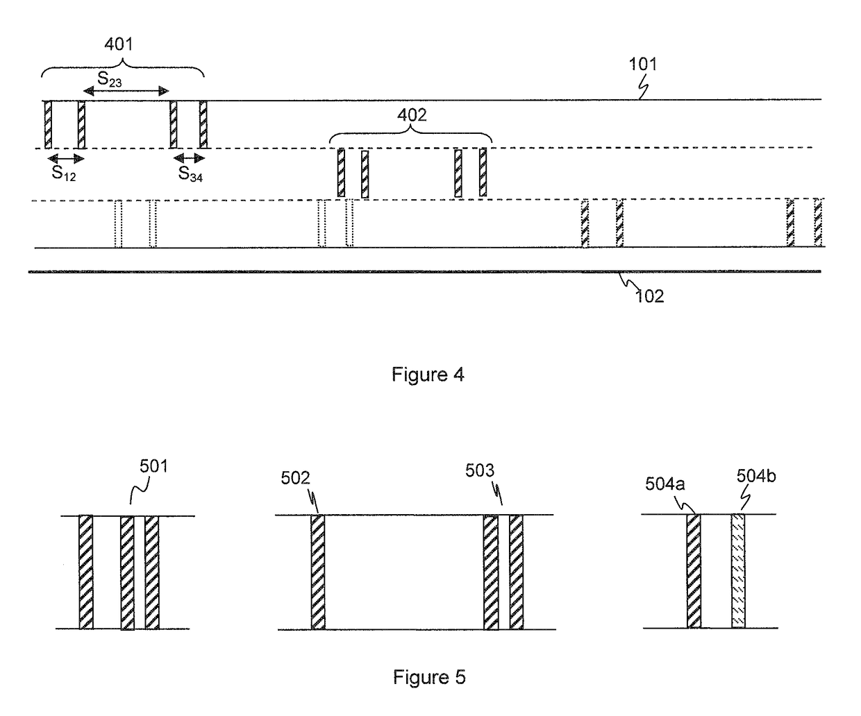
The present application relates to road traffic monitoring to detect the number, speed and / or type of vehicles travelling on a road. Noise features (104) are deployed on, or formed in, the surface of a road (101). The noise feature (104) is arranged to generate a characteristic acoustic signature when traversed by the wheels of a vehicle (105) travelling within a lane of the road. A distributed acoustic sensor (102, 103) is deployed to detect occurrences of the characteristic acoustic signature. In some embodiments the noise element may comprise at least two distinct elements (104a, 104b), for instance rumble strips arranged transversely to the road, which are a known distance apart along the road. The acoustic signals from a wheel crossing both elements can be detected and used to determine the vehicle speed. The number of vehicle axles and axle separation can also be determined to categorize the type of vehicle. A plurality of noise features may be located in different lanes of a multi-lane road with noise features in different lanes arranged to generate different characteristic acoustic signatures.

Description

FIELD OF THE INVENTION[0001]This application relates to apparatus and methods for traffic monitoring, especially for road traffic monitoring using distributed acoustic fibre optic sensing.BACKGROUND OF THE INVENTION[0002]There are various applications where it is desirable to monitor traffic flow along one or more roads. For instance there may be a desire to determine the amount of traffic on a given part of a road network and / or the flow of the traffic on that part of the network. Such information may be required for implementing adaptive traffic management techniques. For instance variable speed limits may be set according to the volume and flow of traffic on a given stretch of road. The operation of traffic lights or other signal controls to control access to a given section of road may be controlled based on knowledge of the traffic flow at various parts of the network. Contraflow systems or other lane controls may be activated or controlled based on such information.[0003]Addit...

Claims


Application Information

Patent Timeline
IPC IPC(8): G08G1/04G01H9/00G08G1/015G08G1/01
CPCG08G1/04G01H9/004G08G1/0125G08G1/0116G08G1/015
Inventor CRICKMORE, ROGERHILL, DAVIDRICHARDS, JONMARTIN, RICHARDMCEWEN-KING, MAGNUS
Owner OPTASENSE HLDG LTD
Learn More