Eureka AIR delivers breakthrough ideas for toughest innovation challenges, trusted by R&D personnel around the world.

Tissue contact sensing with a multi electrode ablation catheter

a multi-electrode ablation and tissue contact technology, which is applied in the field of tissue contact sensing with a multi-electrode ablation catheter, can solve the problems of high cost of imaging equipment, time-consuming, and wide variation between patients, and achieves the effect of reducing the risk of infection, and reducing the patient's comfor

Active Publication Date: 2019-01-22
MEDTRONIC ABLATION FRONTIERS
View PDF71 Cites 6 Cited by
  • Summary
  • Abstract
  • Description
  • Claims
  • Application Information

AI Technical Summary

Problems solved by technology

However, this method requires costly imaging equipment and can be time consuming.
Other methods of electrode-tissue contact assessment involve monitoring the temperature of and power delivered to each electrode, but such methods are typically used after the delivery of ablation energy has already begun and often do not prevent unintended tissue damage.
Additionally, these methods can be ineffective and subject to wide variation between patients.
Difficulties arise when attempting to make impedance measurements via catheters, especially those with a high electrode count (for example, 16-electrode catheters).
Currently known systems and methods do not perform impedance disambiguation, with no discernment between unipolar and bipolar impedance and separation of these from parasitic impedances for multi-electrode catheters.
Thus, a physician cannot attribute an impedance rending to the catheter, let alone to a specific location corresponding to catheter electrodes.
As a result, the physician cannot infer lesion quality.
Beyond the desired unipolar and bipolar results that can be related to their respective electrodes, there are additional undesired parasitic pathways that act to corrupt the desired impedance renderings.

Method used


Image

  • Tissue contact sensing with a multi electrode ablation catheter
  • Tissue contact sensing with a multi electrode ablation catheter
  • Tissue contact sensing with a multi electrode ablation catheter

Examples


Embodiment Construction

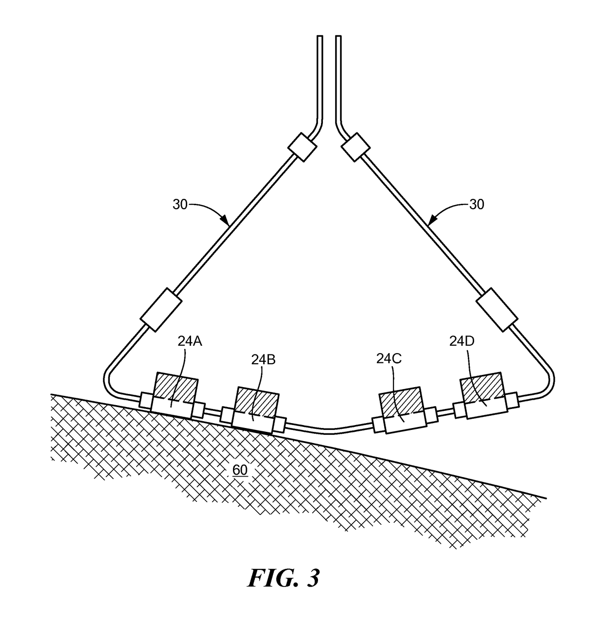
[0036]Referring now to FIGS. 1-3, an exemplary system for assessing electrode-tissue contact is shown. The system 10 may generally include a treatment device, such as an ablation catheter 12, for thermally treating an area of tissue and a console 14 that houses various system controls. The system 10 may be adapted for the use of one or more energy modalities, such as radiofrequency (RF) ablation, cryoablation, electroporation, pulsed field ablation, and / or microwave ablation.

[0037]The ablation catheter 12 may include an elongate body 16 having a distal portion 18 and a proximal portion 20. The distal portion 18 may include a treatment assembly 22 with one or more ablation electrodes 24. For example, the treatment assembly 22 may include one or more carrier arms 30 each bearing one or more ablation electrodes 24. Although not shown, one or more of the carrier arms 30 may also bear one or more mapping electrodes, pacing electrodes, reference electrodes, radiopaque markers, sensors (su...


PUM


Abstract

A method and system for assessing electrode-tissue contact before the delivery of ablation energy. The system may include a control unit programmed to determine a difference between a maximum impedance magnitude at a low frequency for a given electrode and an absolute minimum impedance magnitude at the low frequency across all electrodes, determine a difference between a maximum impedance magnitude at a high frequency for a given electrode and an absolute minimum impedance magnitude at the high frequency across all electrodes, and determine a difference between a maximum impedance phase at the high frequency for a given electrode and an absolute minimum impedance phase at the high frequency across all electrodes. Differences may be correlated to one another using a linear model, the results determining electrode-tissue contact status. The results may be displayed in a graphical format for easy communication to the user.

Description

CROSS-REFERENCE TO RELATED APPLICATION[0001]n / aSTATEMENT REGARDING FEDERALLY SPONSORED RESEARCH OR DEVELOPMENT[0002]n / aFIELD OF THE INVENTION[0003]The present invention relates to a method and system for assessing electrode-tissue contact before the delivery of ablation energy.BACKGROUND OF THE INVENTION[0004]Many types of cardiac arrhythmia, conditions in which the heart's normal rhythm is disrupted, are often treated by ablation (for example, radio frequency (RF) ablation, cryoablation, ultrasound ablation, laser ablation, microwave ablation, and the like), either epicardially or endocardially. Cardiac ablation may be performed with a variety of devices, such as devices having expandable distal ends. For example, ablation of the tissue surrounding a pulmonary vein ostium may be performed with a device having a distal end that is expandable into a substantially circular configuration, such as the pulmonary vein ablation catheter (PVAC®, Medtronic, Inc., Minneapolis, Minn.).[0005]Ho...

Claims


Application Information

Patent Timeline
Patent Type & Authority Patents(United States)
IPC IPC(8): A61B5/06A61B18/12A61B5/00A61B8/14A61B5/053A61B18/14A61B18/00
CPCA61B5/068A61B5/6852A61B5/6869A61B5/6886A61B5/7225A61B5/7246A61B18/1206A61B5/0538A61B2562/04A61B5/7275A61B5/743A61B18/1492A61B2018/0016A61B2018/00267A61B2018/00351A61B2018/00577A61B2018/00654A61B2018/00672A61B2018/00678A61B2018/00702A61B2018/00839A61B2018/00875A61B2018/00904A61B2018/00982A61B2018/1467A61B2562/0209
Inventor CONDIE, CATHERINE R.FRAASCH, STEVEN J.SHERMAN, MARSHALL L.REHBERGER, TRENTON JAYWEYRAUCH, CORINNE
Owner MEDTRONIC ABLATION FRONTIERS
Why Eureka
Eureka Blog
Learn More