Method and device for monitoring an electrical network in a rail vehicle, and rail vehicle

a technology for rail vehicles and electrical networks, applied in the direction of emergency protective circuit arrangements, electrical devices, circuit arrangements, etc., can solve the problems of undesirable destruction of rail vehicle components, and achieve the effect of high operational safety

Active Publication Date: 2018-12-11
BOMBARDIER TRANSPORTATION GMBH
View PDF15 Cites 0 Cited by
  • Summary
  • Abstract
  • Description
  • Claims
  • Application Information

AI Technical Summary

Benefits of technology

[0057]Also provided is a rail vehicle, the rail vehicle comprising the device described above. This advantageously results in a rail vehicle having high operational safety.

Problems solved by technology

In the event of short circuits, so-called electric arcs may also occur that may lead to the undesirable destruction of components of the rail vehicle.
The technical problem exists of creating a device and a method for monitoring an electrical network of a rail vehicle as well as a rail vehicle, the device and method enabling the alternative yet reliable and rapid detection of a network error.
Furthermore, the technical problem exists of enabling the localization of a network error to provide improved error management.

Method used


Image

  • Method and device for monitoring an electrical network in a rail vehicle, and rail vehicle
  • Method and device for monitoring an electrical network in a rail vehicle, and rail vehicle
  • Method and device for monitoring an electrical network in a rail vehicle, and rail vehicle

Examples


Embodiment Construction

[0062]Below, identical reference numbers refer to elements having the same or similar technical features.

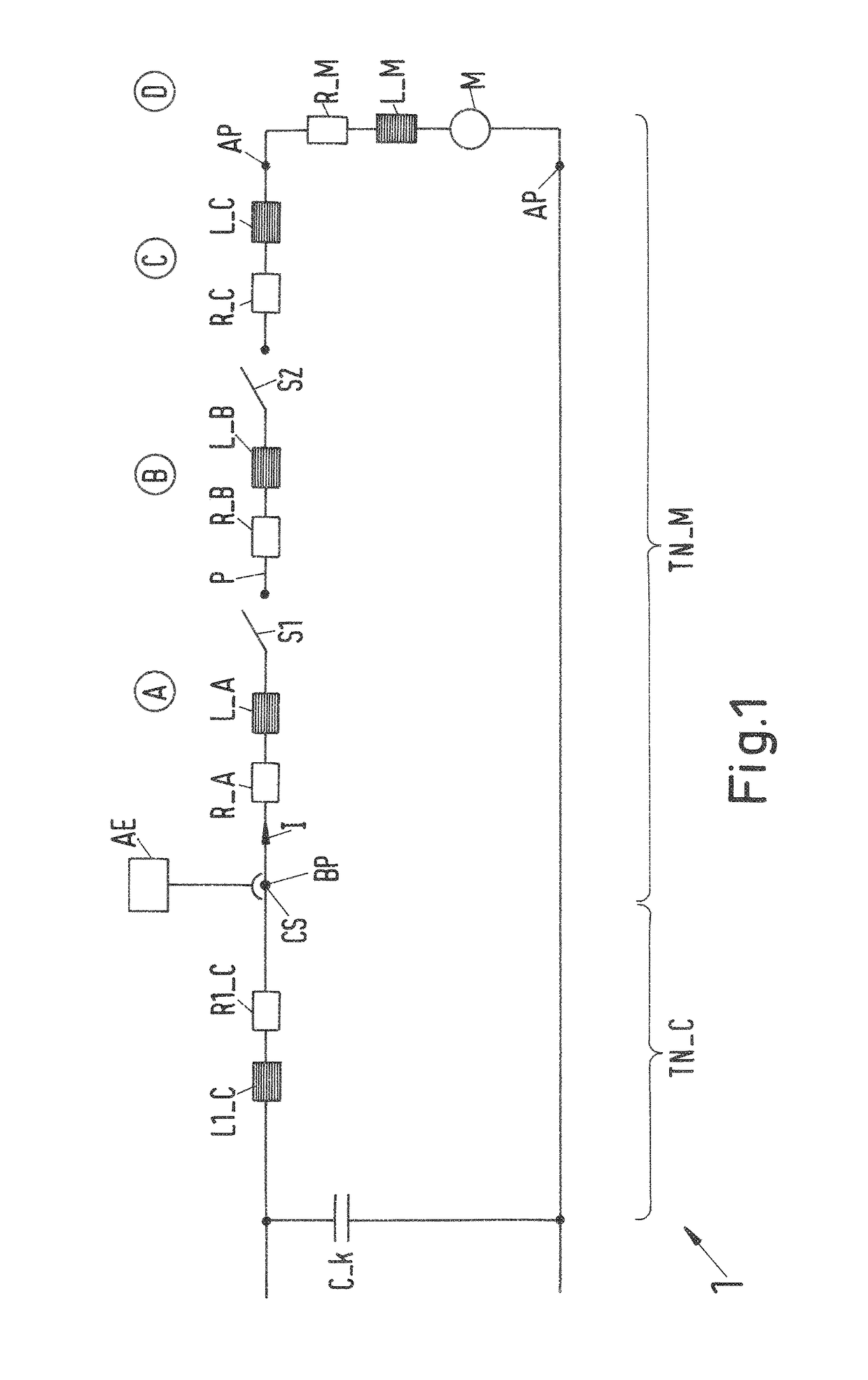
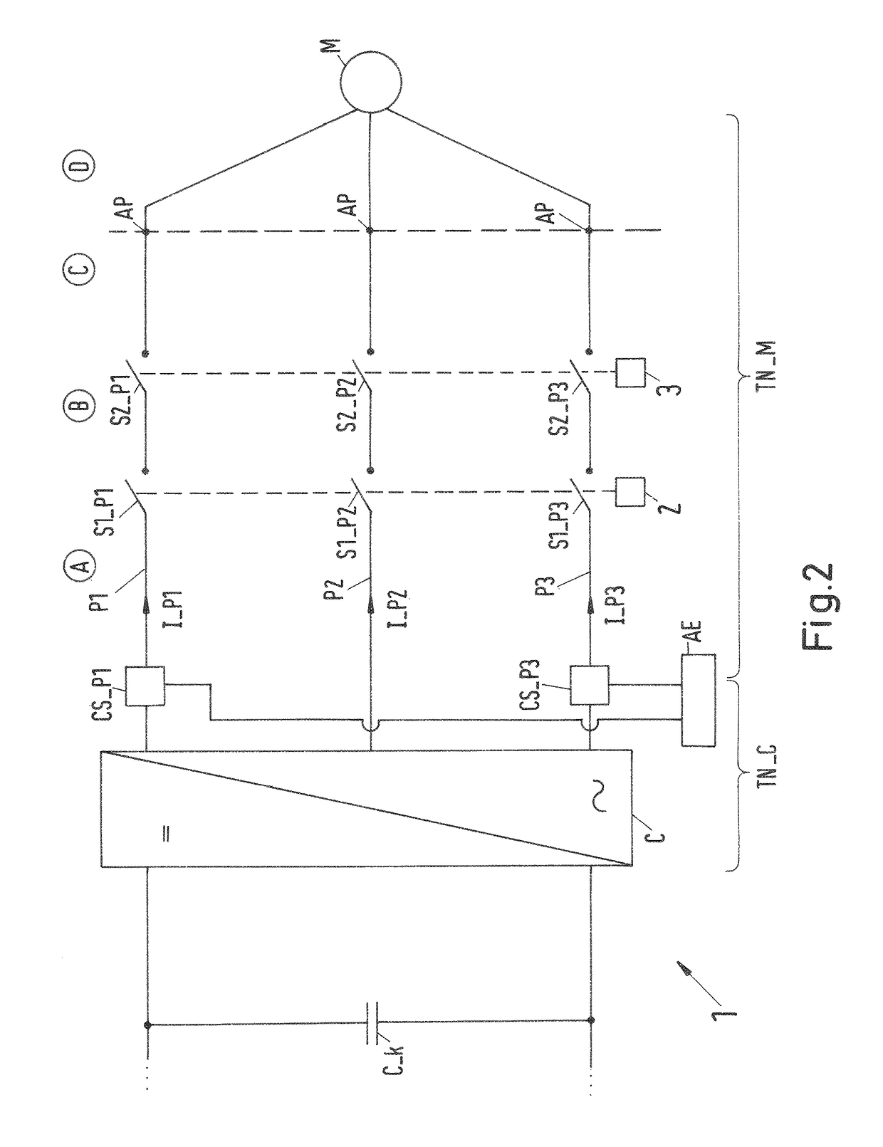
[0063]In FIG. 1, an equivalent circuit diagram of the electrical network 1 of a rail vehicle (not shown) is illustrated. This is a 2-phase system, the electrical components of a feed and return line in the upper phase line being summarized. The electrical network 1 comprises a power converter C (see FIG. 2), a resulting inductance L1_C and a resulting resistance R1_C of the power converter C being shown in FIG. 1. Also shown is an intermediate circuit capacitor C_k. Furthermore, the electrical network 1 comprises a permanent magnet machine M, a resulting inductance L_M and a resulting resistance R_M of the permanent magnet machine M also being shown. Also shown is a phase line P having a first section A, a second section B and a third section C.

[0064]Also shown are a current sensor CS and an evaluation device AE. The current sensor CS detects a current value in a determination po...


PUM


Abstract

The invention relates to a device and to a method for monitoring an electrical network in a rail vehicle. The electrical network includes at least one converter, at least one drive motor, at least one first phase line for electrical connection of the at least one converter and the at least one drive motor. A magnitude of a current change of a first phase current is determined. A network error in a partial network on the machine side is detected if at least one criterion based on the current change is met. The criterion based on a current change is met when the magnitude of the current change of the first phase current is greater than a predetermined current change threshold.

Description

CROSS-REFERENCE TO RELATED APPLICATIONS[0001]This application is the United States national phase of International Application No. PCT / EP2015 / 071817 filed Sep. 23, 2015, and claims priority to German Patent Application No. 10 2014 219 278.1 filed Sep. 24, 2014, the disclosures of which are hereby incorporated in their entirety by reference.BACKGROUND OF THE INVENTIONField of the Invention[0002]The invention relates to a method and a device for monitoring an electrical network in a rail vehicle as well as to a rail vehicle.Description of Related Art[0003]In rail vehicles, both asynchronous and synchronous machines, including so-called permanent magnet machines (PMM), which are also referred to as permanent magnet motors, are used to drive the rail vehicle. The machines used to drive the rail vehicle are also referred to hereinafter as drive motors. These machines are supplied with electrical energy by a generally three-phase electrical network. The electrical network also comprises a...

Claims


Application Information

Patent Timeline
Patent Type & Authority Patents(United States)
IPC IPC(8): H02H7/08H02H3/44H02H3/027H02H7/085H02H7/122H02H7/26
CPCH02H3/44H02H3/027H02H7/08H02H7/0854H02H7/26H02H7/0858H02H7/122H02H7/1227H02H7/0857
Inventor ISEPPONI, GERHARD
Owner BOMBARDIER TRANSPORTATION GMBH
Why Eureka
Try Eureka