Transmission for a Twin-Screw Extruder

a technology of twin-screw extruder and transmission device, which is applied in the direction of toothed gearing, belt/chain/gearing, gearing, etc., can solve the problems of affecting the performance of the gear, the teeth of the gear cannot be mitigated, and the gear with relatively small diameter can be placed

Inactive Publication Date: 2008-12-18
THEYSOHN EXTRUSIONSTECHNIK GMBH
View PDF6 Cites 2 Cited by
  • Summary
  • Abstract
  • Description
  • Claims
  • Application Information

AI Technical Summary

Benefits of technology

[0009]It is the object of the invention to avoid these disadvantages and to provide a...

Problems solved by technology

The problem with driving twin-screw extruders lies in the fact that two drive shafts that are very close to each other have to transfer very high torques.
Only a gear with relatively small diameter can be put on the short drive shaft, as it would otherwise interfere with the long drive shaft.
The forces on this gear are extremely large with high torque.
The pressure on the teeth of the gear can only be mitigated in a limited manner by making the gear longer (longitudinally of the drive shaft), but since the drive shaft will twist at high torque, only one portion of the length of the gear will ...

Method used


Image

  • Transmission for a Twin-Screw Extruder
  • Transmission for a Twin-Screw Extruder
  • Transmission for a Twin-Screw Extruder

Examples


Embodiment Construction

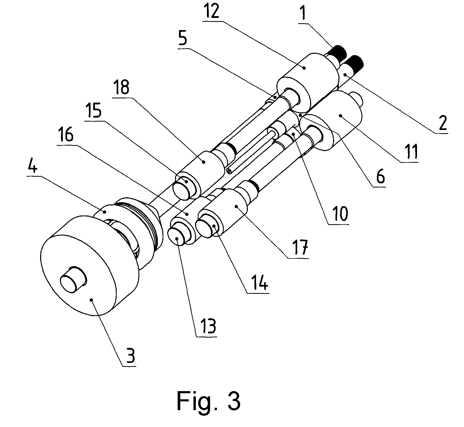
[0020]An input gear 3 is rotationally fixed on a long drive shaft 1, meshing with an unillustrated output gear of a motor, or the long drive shaft 1 is coupled directly with a drive motor. Furthermore, the long drive shaft 1 carries an axial bearing 4 and is rotationally fixed to an output gear 5 that meshes with a gear 6 rotationally fixed to a short drive shaft 2. The short drive shaft 2 also has an axial bearing 9. This is limited in diameter due to the closeness of the long drive shaft 1 and is preferably designed as a double bearing.

[0021]The output gears 5 and 6 have helical gear teeth. This helical gearing is selected such that the short drive shaft 2 is pushed toward the respective screw and thus the axial forces working on the bearing 9 of the short drive shaft 2 become proportionally smaller with rising torque. As a result, the axial forces on the long drive shaft 1 do increase, but this is not problematic since the axial bearing 4 can be made larger.

[0022]As can be seen f...


PUM

PropertyMeasurementUnit
Angleaaaaaaaaaa
Angleaaaaaaaaaa
Angleaaaaaaaaaa

Abstract

Gear system for driving screws of a twin-screw extruder with two parallel drive shafts (1, 2) of different length, of which the longer drive shaft (1) bears a drive gear wheel (3). The shorter drive shaft (2) has rotationally fixed connection by way of a pinion (6) to three distributor shafts (13, 14, 15), which can be driven from the longer drive shaft (1) by way of an annular gear wheel (20) which has internal teeth (19) and, on the distributor shafts (13, 14, 15), gear wheels (16, 17, 18) intermeshing with these teeth. On the longer drive shaft (1), there is a pinion (5) directly intermeshing with the pinion (6) of the shorter drive shaft (2). In order to achieve good division of the loads, the annular gear wheel (20) also has outer teeth (21) which intermesh with gear wheels (22, 23) of two intermediate shafts (24, 25), which intermesh by way of further gear wheels (26, 27) with the drive gear wheel (3).

Description

TECHNICAL FIELD[0001]The invention refers to a transmission according to the preamble of claim 1.STATE OF THE ART[0002]The problem with driving twin-screw extruders lies in the fact that two drive shafts that are very close to each other have to transfer very high torques. Both drive shafts of the transmission have different lengths. A drive gear of virtually any size can be put on the long drive shaft so that the forces effective on this drive gear (as a result of its large diameter) can be kept within reasonable limits in spite of the high torque. Only a gear with relatively small diameter can be put on the short drive shaft, as it would otherwise interfere with the long drive shaft. The forces on this gear are extremely large with high torque. The pressure on the teeth of the gear can only be mitigated in a limited manner by making the gear longer (longitudinally of the drive shaft), but since the drive shaft will twist at high torque, only one portion of the length of the gear w...

Claims


Application Information

Patent Timeline
IPC IPC(8): F16H37/06B29C48/03
CPCB29C47/0009Y10T74/19098F16H1/227B29C47/0801B29C48/03B29C48/252F16H1/22
Inventor SCHNABL, ERWIN
Owner THEYSOHN EXTRUSIONSTECHNIK GMBH
Why Eureka
Try Eureka