
LED driver circuit, and LED arrangement and a driving method

a technology of led driver circuit and led arrangement, applied in the direction of electric variable regulation, process and machine control, instruments, etc., can solve the problem of higher power loss of driving the switch, and achieve the effect of high resistance valu

Active Publication Date: 2018-10-16
SIGNIFY HLDG BV
View PDF7 Cites 0 Cited by
  • Summary
  • Abstract
  • Description
  • Claims
  • Application Information

AI Technical Summary

Benefits of technology

This patent describes a driver circuit for a main switch that uses a flyback ringing choke converter for efficient and low cost operation. The driver ensures that power loss is kept low by ramping up the base current of the main transistor and using a base capacitor to quickly enter a saturation status and quickly switch off the main transistor. The circuit also includes a second capacitor discharge circuit to reset the circuit after the ramp has been used to turn on the main transistor. The driver circuit uses a linearly varied driving current to reduce power loss from voltage to current conversion. Overall, this driver circuit improves the efficiency, reliability, and control of the main switch.

Problems solved by technology

In the above typical self-oscillation converter, the power loss in driving the switch becomes higher if the oscillated element provides excessive current / voltage.
This problem occurs more often when the converter is used with a wide input voltage range such as universal mains.

Method used


Image

  • LED driver circuit, and LED arrangement and a driving method
  • LED driver circuit, and LED arrangement and a driving method
  • LED driver circuit, and LED arrangement and a driving method

Examples


Embodiment Construction

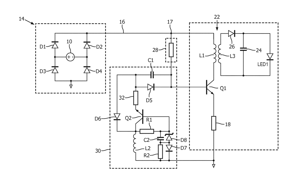
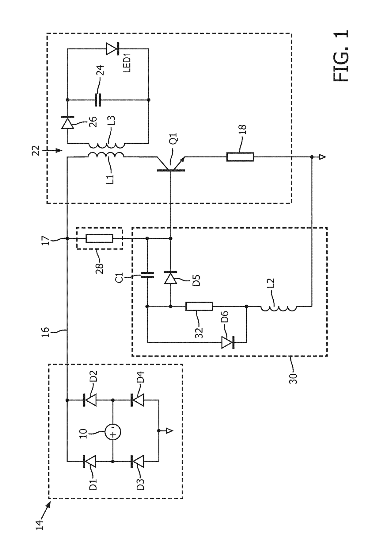
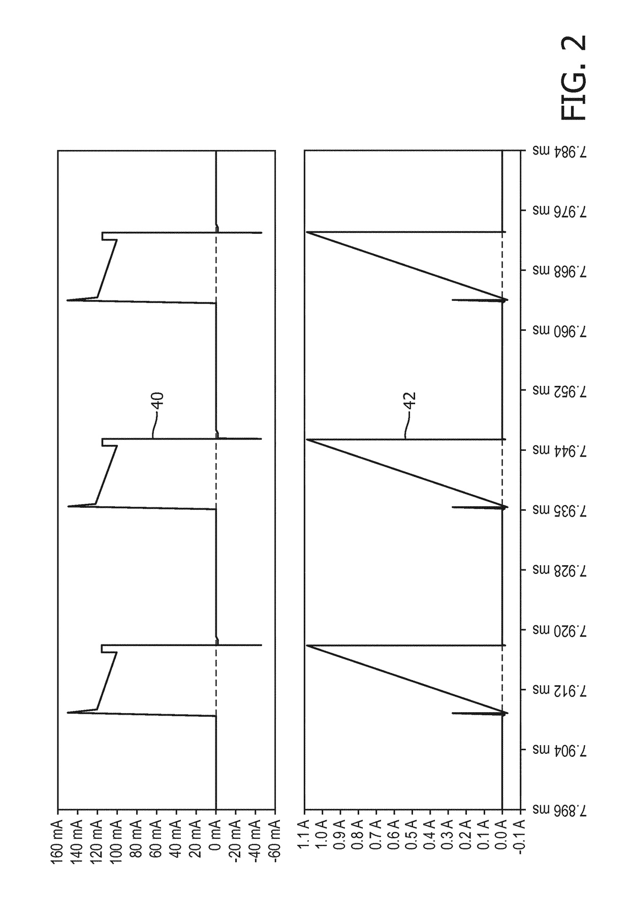
[0045]The invention provides a driver circuit for driving an LED arrangement which uses a switch mode power converter, for example a flyback ringing choke converter, which comprises a main switch (e.g. bipolar transistor) and a sub-circuit for generating a current for the control terminal of the main switch. The sub-circuit in some examples makes use of an auxiliary winding as a voltage supply, and further comprises a ramp circuit for generating a ramp voltage from the voltage supply and a voltage follower, such as a control transistor, connected between the voltage supply and the control input of the main switch. By ramping up the current supplied to the main switch control input, the losses arising as a result of the current flowing to the control input of the main switch are reduced.

[0046]The invention will be explained with reference to one preferred type of switch mode power converter; the ringing choke converter (RCC). The invention may be applied to other self-oscillating swi...


PUM


Abstract

The invention provides a driver circuit for driving an LED arrangement which uses a switch mode power converter, for example a flyback ringing choke converter, which comprises a main switch (e.g. bipolar transistor) and a sub-circuit for generating a current for the control terminal of the main switch. The sub-circuit in some examples makes use of an auxiliary winding as a voltage supply, and further comprises a ramp circuit for generating a ramp voltage from the voltage supply and a voltage follower, such as a control transistor, connected between the voltage supply and the control input of the main switch. By ramping up the current of the main switch, the losses arising as a result of the current flowing to the control input of the main switch are reduced. One set of examples makes use of a flyback ringing choke converter, which enables low cost implementation and good efficiency. The driver is able to receive a wide range of input voltages, by ensuring that the power loss is kept low. In particular, by ramping up the control current of the main switch, the losses arising as a result of the current flowing are reduced.

Description

CROSS-REFERENCE TO PRIOR APPLICATIONS[0001]This application is the U.S. National Phase application under 35 U.S.C. § 371 of International Application No. PCT / EP2016 / 061832, filed on May 25, 2016, which claims the benefit of International Application No. PCT / CN2015 / 080043, filed on May 28, 2015 and European Patent Application No. 15192086.5, filed on Oct. 29, 2015. These applications are hereby incorporated by reference herein.FIELD OF THE INVENTION[0002]This invention relates to LED-based lighting.BACKGROUND OF THE INVENTION[0003]LED-based (retrofit) lamps are used more and more in home buildings and offices. Besides their high efficiency they also attract consumers due to new design features, different color temperatures, dimming ability etc.[0004]To fit LED lighting to existing mains lighting fixtures, each LED light unit makes use of a converter circuit, for converting the AC mains into a DC drive signal, and also for reducing the voltage level.[0005]The converter circuit typical...

Claims


Application Information

Patent Timeline
Patent Type & Authority Patents(United States)
IPC IPC(8): H05B33/08H02M3/335H02M3/338H02M3/33H05B44/00
CPCH05B33/0815H02M3/33507H02M3/3381Y02B20/30H05B45/385H05B45/3725
Inventor ZHANG, HUICLAESSENS, DENNIS JOHANNES ANTONIUS
Owner SIGNIFY HLDG BV
Learn More