
Floating evaporation pan with adjustable freeboard and surrounding wave-guard

a floating evaporation pan and wave guard technology, applied in the field of measuring evaporation rates for fluids, can solve the problems of large unknown in the management of large bodies of fluid, the amount of fluid lost to evaporation, and the disturbance of sloshing within the pan, so as to enhance the accuracy and reliability of evaporation measurements, and reduce fluid sloshing

Active Publication Date: 2018-09-25
COLLISON JACOB WILLIAM
View PDF5 Cites 0 Cited by
  • Summary
  • Abstract
  • Description
  • Claims
  • Application Information

AI Technical Summary

Benefits of technology

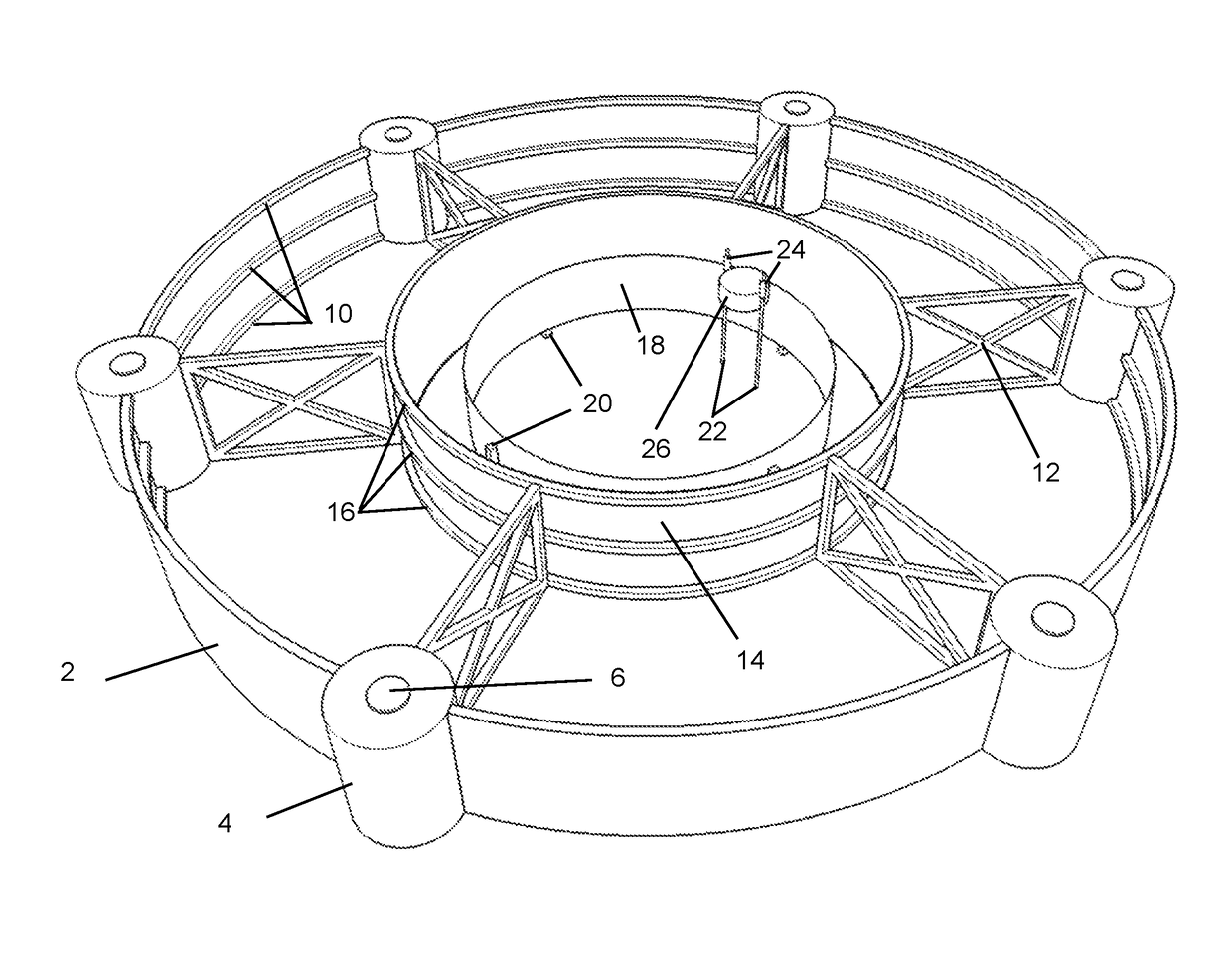
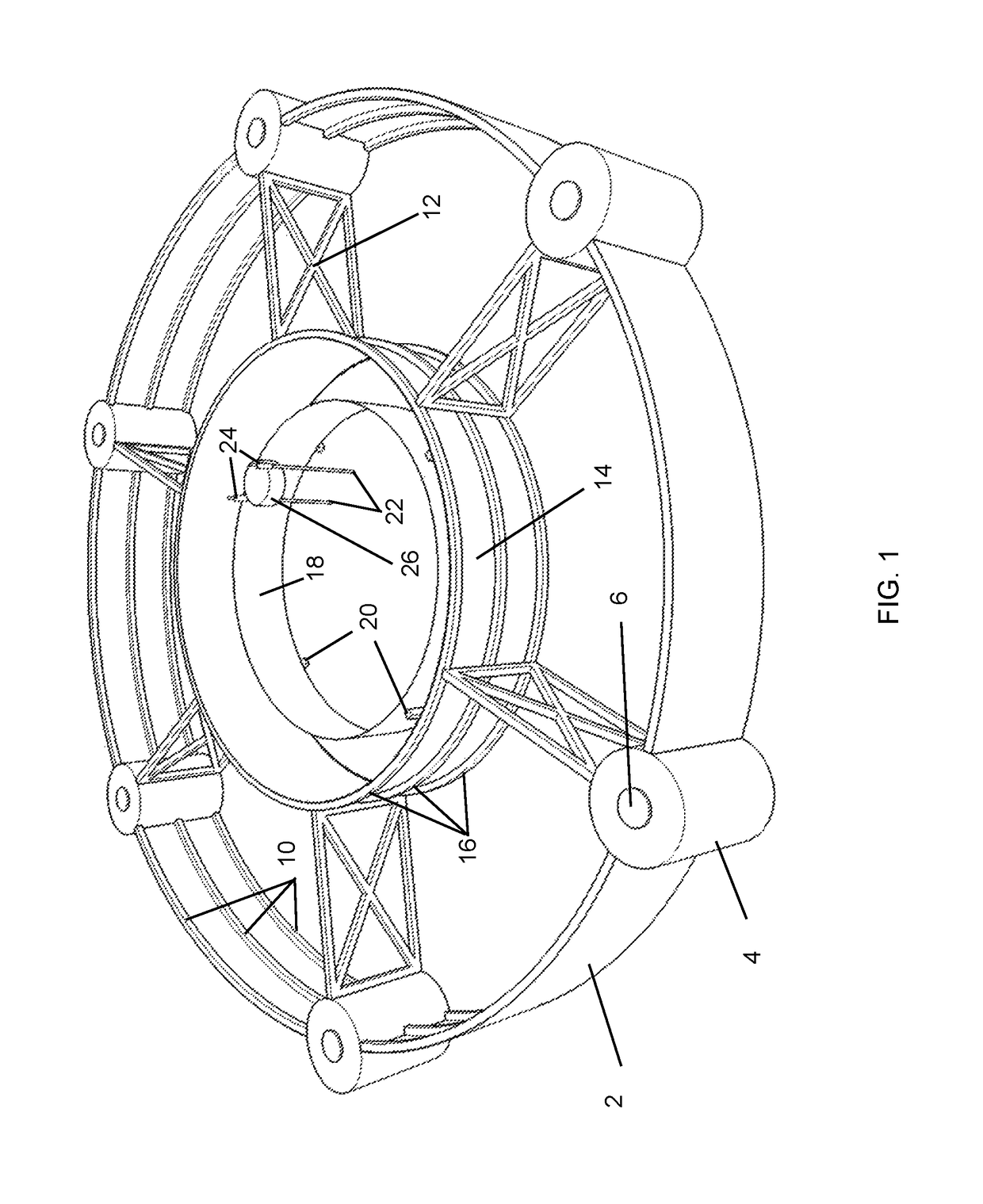
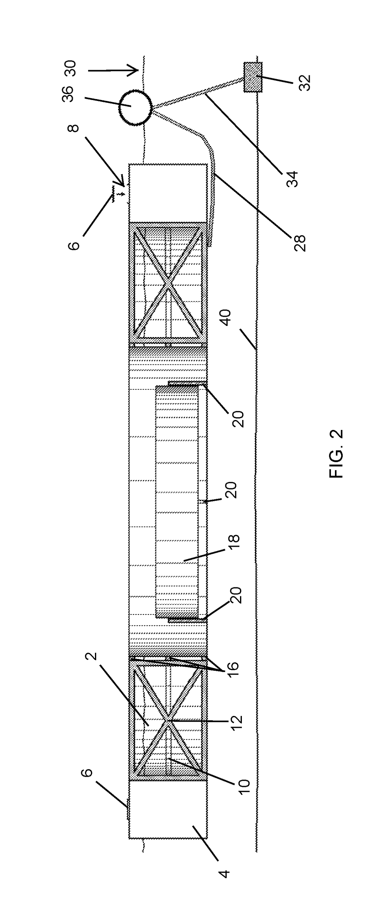
The present invention provides an improved evaporation pan assembly for measuring evaporation rates in large, open bodies of fluid. The assembly includes a floating evaporation pan with adjustable buoyancy floats attached to a wave guard and a full-circumference splash guard. A baffle system reduces sloshing and a pump controls the fluid level within the pan. The freeboard of the pan can be adjusted to match the level of the surrounding body of fluid. The assembly also includes an anchoring system to prevent movement and a heating system to control the fluid temperature. These techniques and methods enhance the accuracy and reliability of evaporation rate calculations.

Problems solved by technology

Typically, the largest unknown in the management of large bodies of fluid (e.g., lakes and reservoirs) is the amount of fluid lost to evaporation.
There are several problems associated with obtaining accurate evaporation rates using a land-based evaporation pan.
Wave action can have two major adverse impacts on the height of the fluid within the pan: 1) wind or human generated waves can overtop the side of the evaporation pan adding fluid to the pan; and, 2) wind or human generated wave action can cause a sloshing disturbance within the pan where fluid within the pan can overtop into the surrounding body of fluid.
In both cases, the measurement of evaporation within the pan is now invalid for the time period where fluid was added or removed, reducing the reliability of the floating evaporation pan.

Method used


Image

  • Floating evaporation pan with adjustable freeboard and surrounding wave-guard
  • Floating evaporation pan with adjustable freeboard and surrounding wave-guard
  • Floating evaporation pan with adjustable freeboard and surrounding wave-guard

Examples


example 1

[0026]An apparatus as described above was constructed of marine grade aluminum, 6061-T6 alloy. There were six floats spaced 60 degrees from each other with wave-guard segments attached between the floats. The floats and wave-guards formed a circular-ring surrounding the evaporation pan. The circular-ring shape of the floats and wave-guard aided in the stability of the apparatus and deflected energy imposed on the apparatus from waves in the body of fluid being evaluated. The spacing-braces attached the circular-ring formed by the floats and wave-guard segments to the evaporation pan. The length of the spacing-braces was sufficiently long to prevent splashing on the wave-guards from being ejected into the evaporation pan. Three mooring systems were attached to the bottom of the spacing-braces where the spacing-braces attached to a float approximately every 120 degrees, and each extending outward from the apparatus along the vector formed by the spacing-brace that it was attached to. ...


PUM


Abstract

An improved evaporation pan assembly and measurement method comprising adjustable buoyancy floats attached to an outer wave-guard that surrounds the evaporation pan. An anchor system preferably restricts lateral movement while allowing for vertical movement with changing fluid levels. Preferably, the evaporation pan assembly further comprises a baffle system within the evaporation pan to prevent sloshing of the fluid within the pan. The height of the body of fluid being evaluated is preferably measured with a guided float assembly within the evaporation pan.

Description

STATEMENT REGARDING FEDERALLY SPONSORED RESEARCH OR DEVELOPMENT[0001]Not Applicable.BACKGROUND OF THE INVENTIONField of the Invention (Technical Field)[0002]Embodiments of the present invention relate in general to methods and apparatuses for measuring evaporation rates for a fluid within a body of fluid, and more particularly to methods and apparatuses that carry out such measurement through a floating evaporation pan within the larger body of the fluid of interest.Description of Related Art[0003]Knowing the amount of evaporation from a body of fluid is critical for its proper management. Typically, the largest unknown in the management of large bodies of fluid (e.g., lakes and reservoirs) is the amount of fluid lost to evaporation. There are many methods of measuring the evaporation rate, each with its own advantages and disadvantages, with the most common method being a land-based evaporation pan. Under normal operation conditions, a land-based evaporation pan is situated near a ...

Claims


Application Information

Patent Timeline
Patent Type & Authority Patents(United States)
IPC IPC(8): G01F23/30G01W1/00
CPCG01F23/303G01W1/00
Inventor COLLISON, JACOB WILLIAM
Owner COLLISON JACOB WILLIAM
Learn More